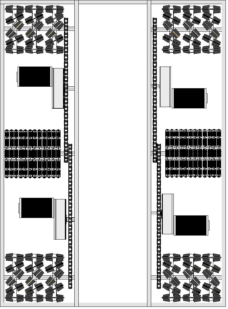
Six Wheel Omni Directional Drive System With a Suspension for
ramps
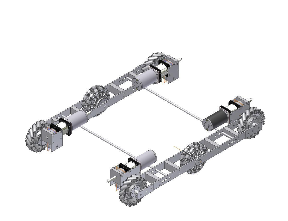
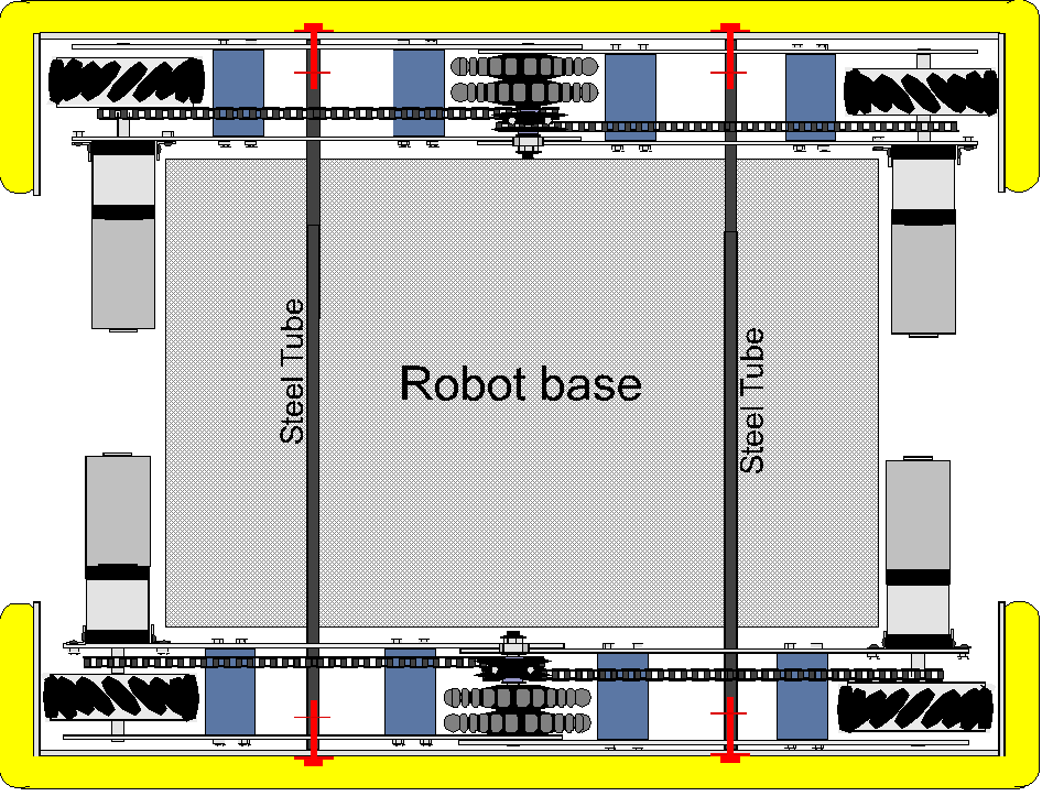
This system will have a six wheel drive system that has a independent
suspension for the corner wheels. The robot will still have the ability of going
all directions including rotate. Note the red dots in the middle of the frame.
This is the location where the steel pipes will go through and support the
robot. The right one is slotted so the suspension can move.
Above: A layout of the robot base. We envision that the bumper bolts will
slide into the steel tubes and cotter pins will hold them on for easy removal.
Note that the drives are clear so they can move up and down for going over
ramps. This drive design requires full contact with the floor. Above Right a
lower cost version, no helical gears. Straight off the BaneBot gear boxes makes
it easy to assemble. Note how the bumpers are attached by pins.
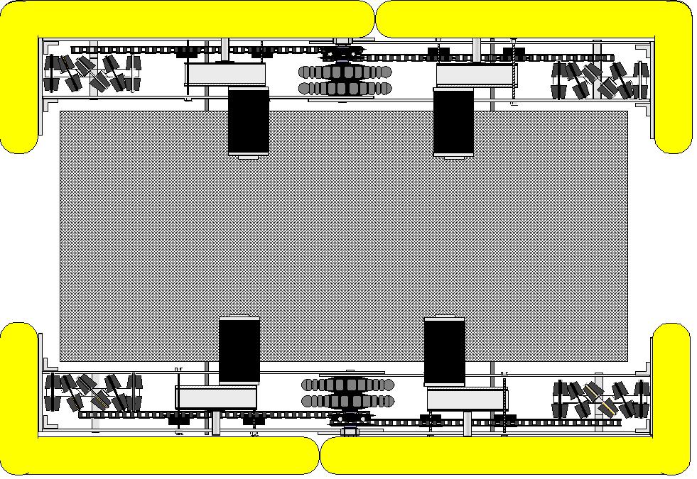
Above: Our third drive design of this system. It is easier and less expensive to build and
allows for chain adjustment by slotting the frame for the gear box mount. This
also with the new motor location gives room front and back for ball pick up or
arm mounting.
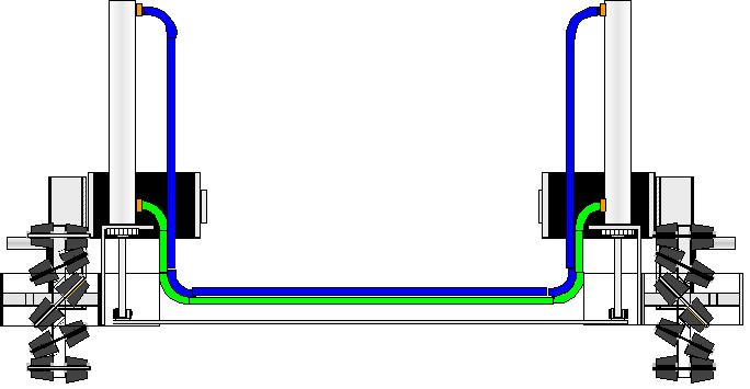
Above: Air suspension. Our latest Idea. Once the air pressure is set to hold
the robot at the needed height when one side moves up air will force the other
side down. This will allow the robot to transition up a ramp on a angle.
Above how about More traction with Omni direction. Maybe too much weight but
it just might work.
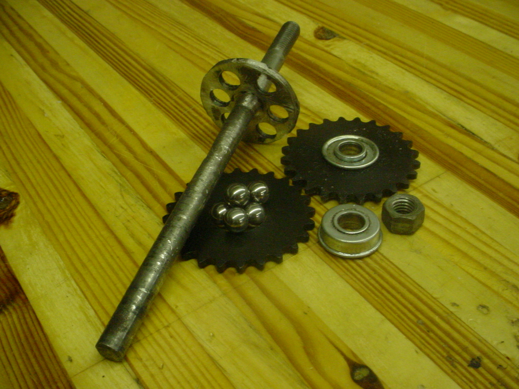
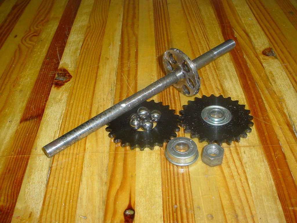
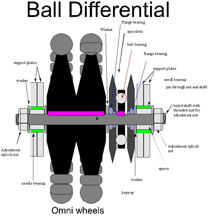
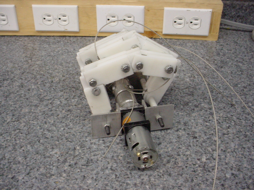
Ball Differential
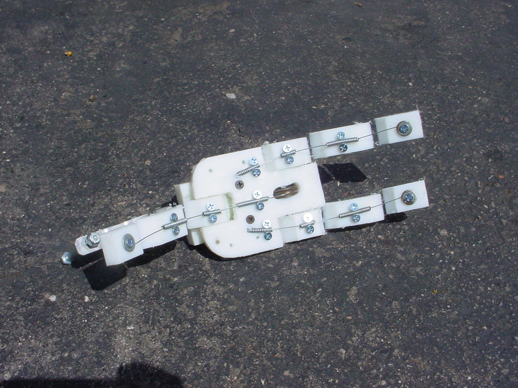
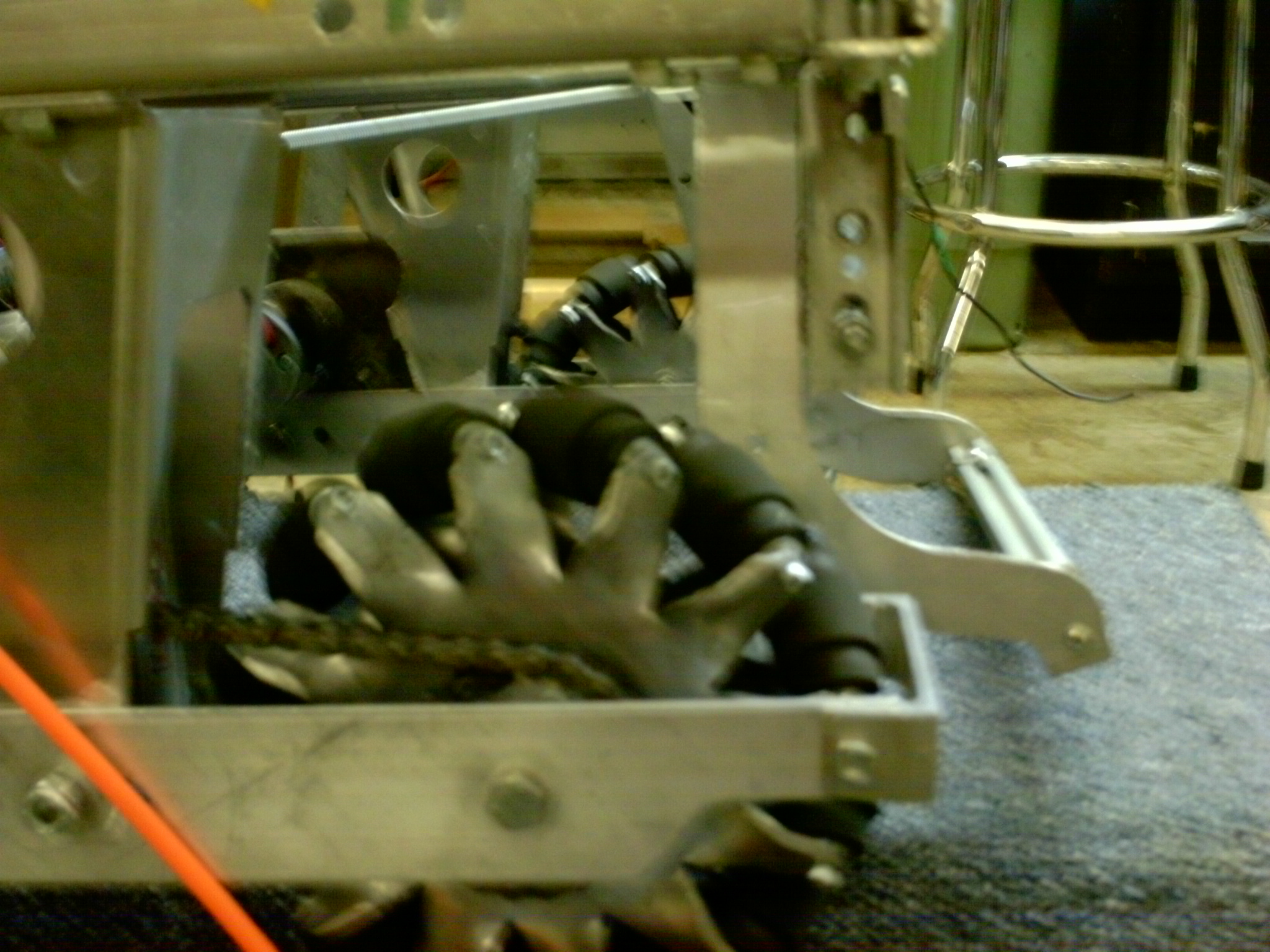
Mechanical Hand
Above is a test model. Below are drawings of an assembly we will build. We
will use cable and pully with spring tension to hold it open.
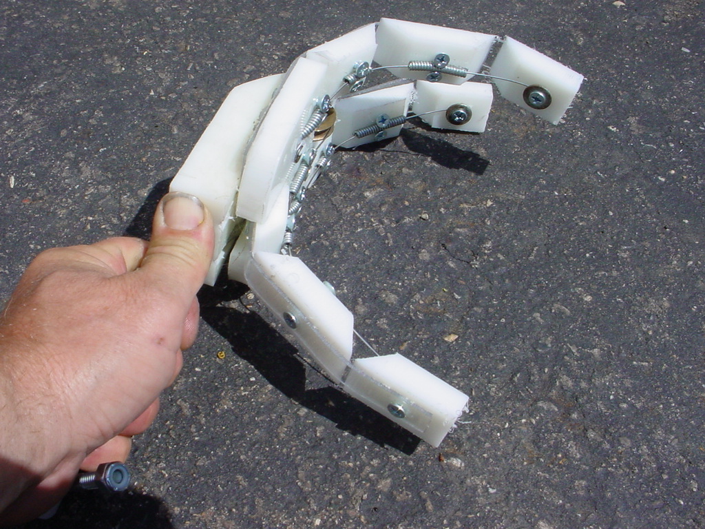
Above: We built the hand design and it did work but the finger tips would
bend before the finger base. Not good for grabbing things. We may remove a
bend joint for easy control.
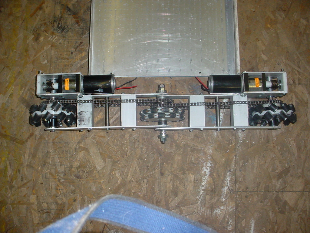
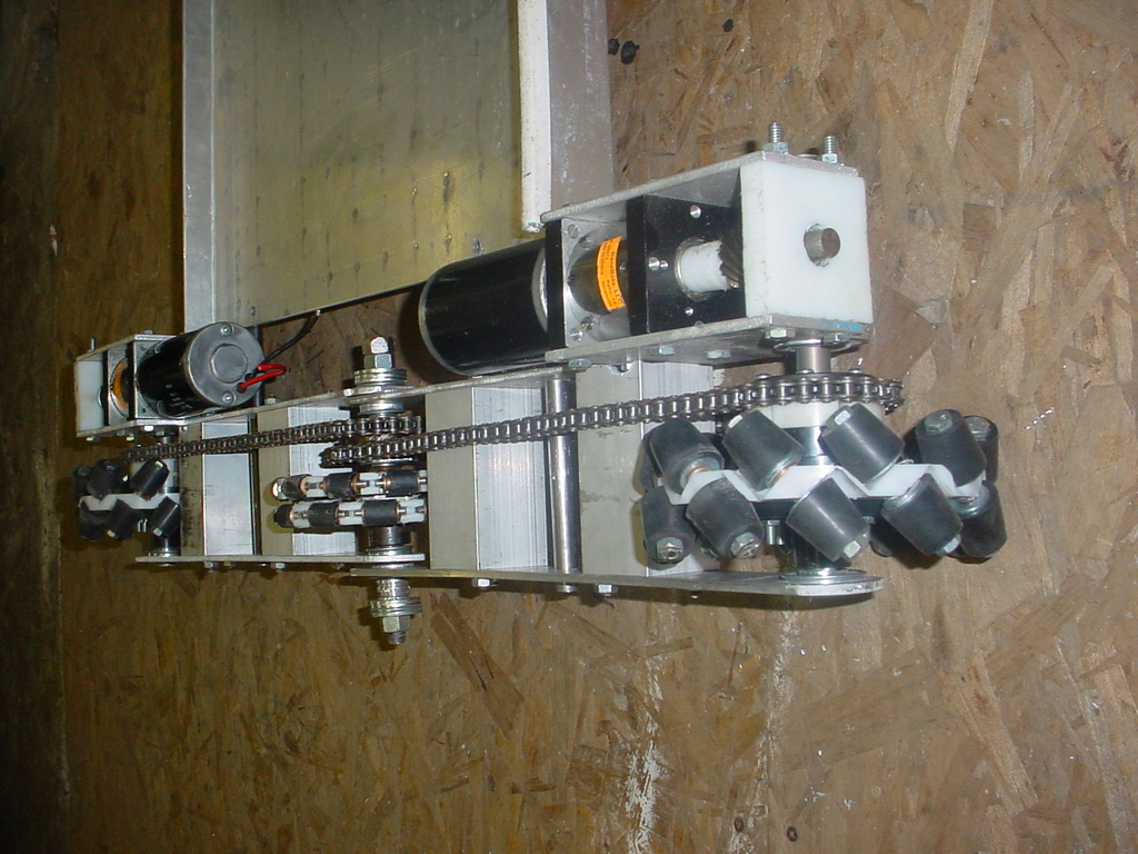
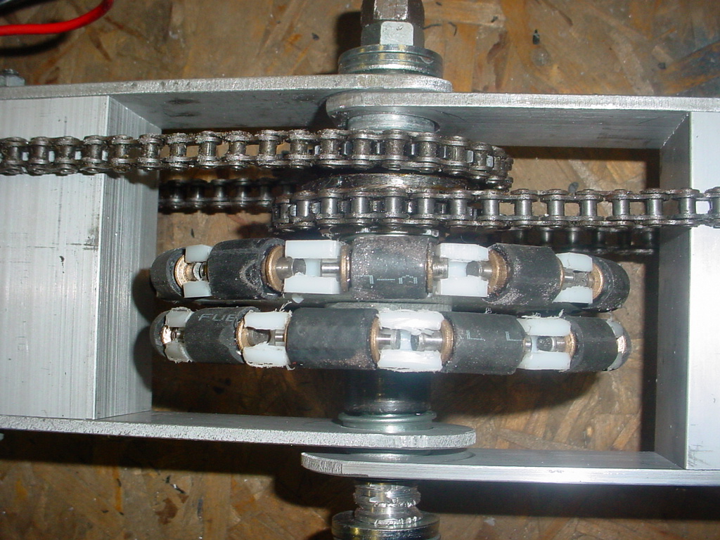
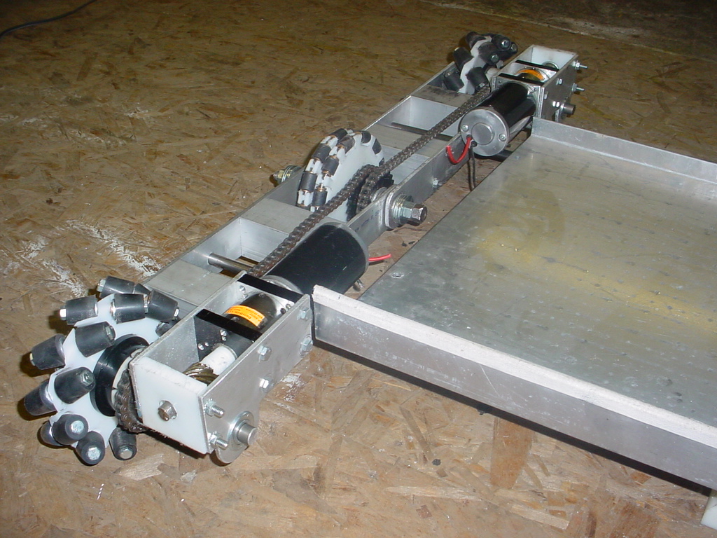
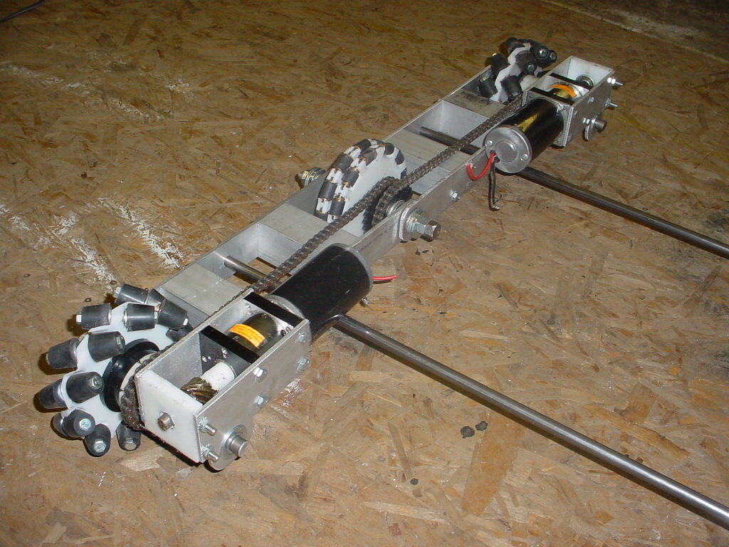
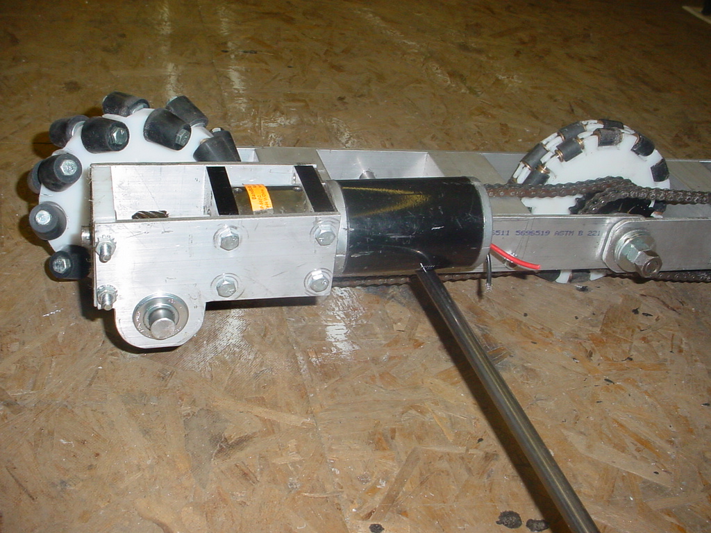
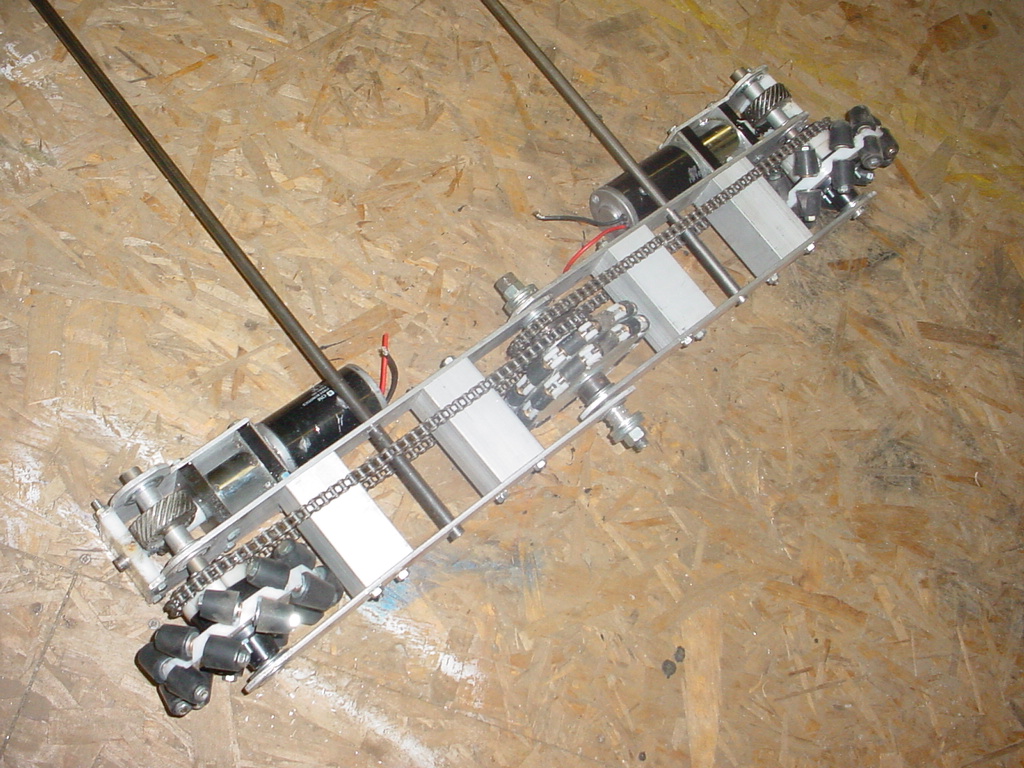
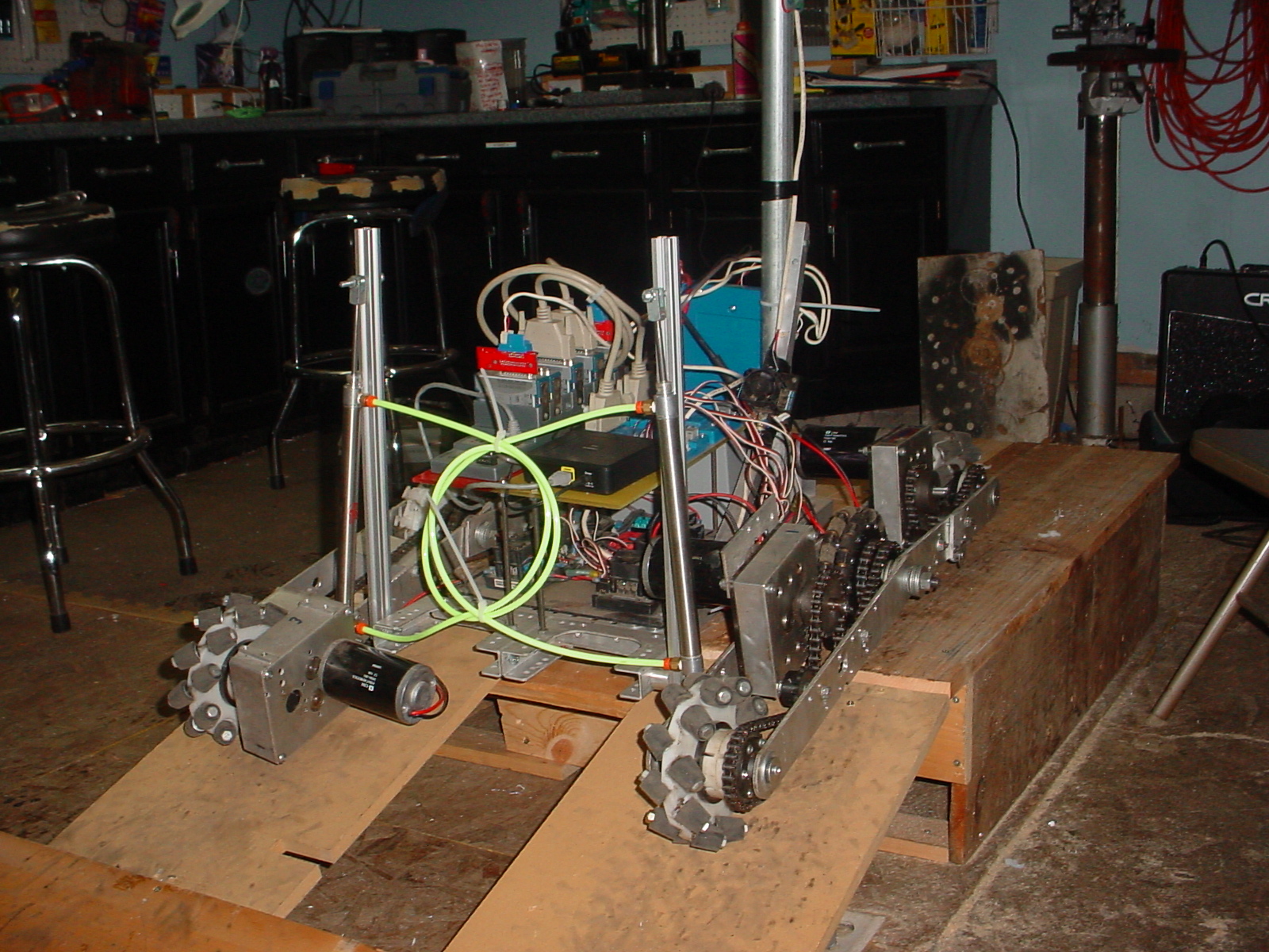
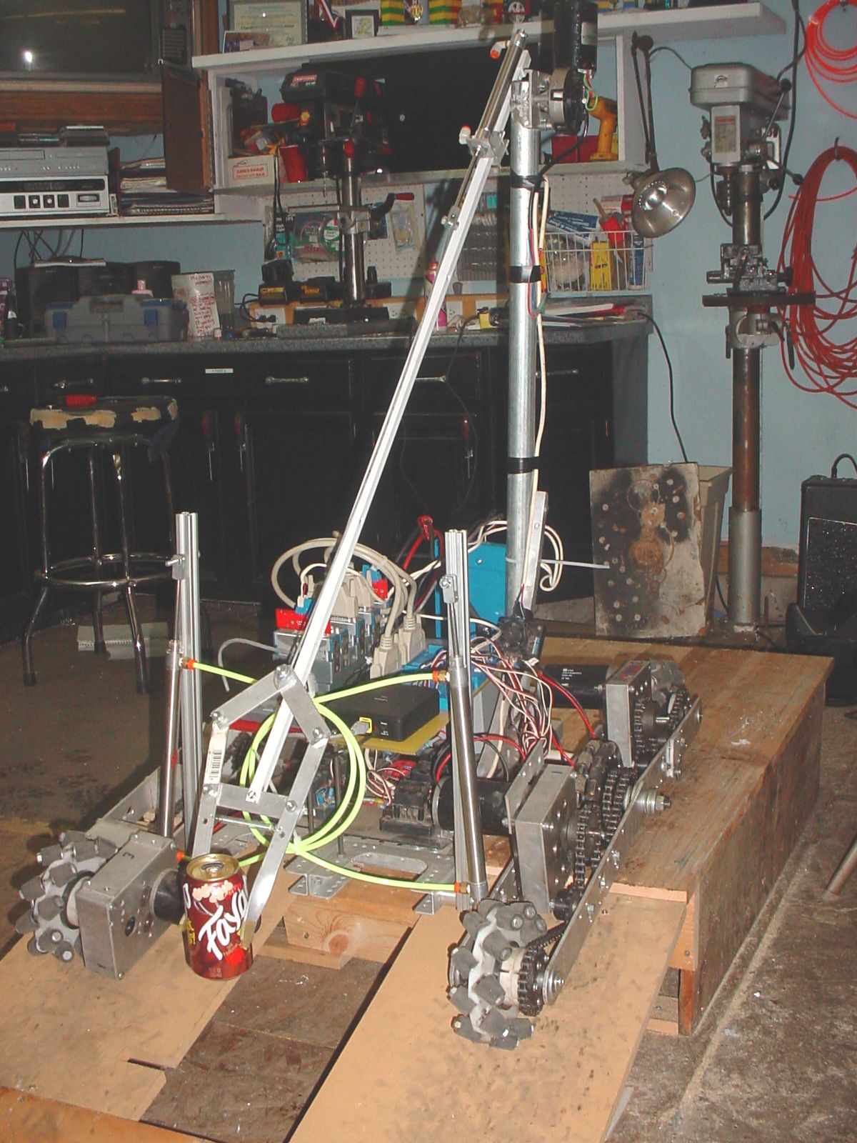
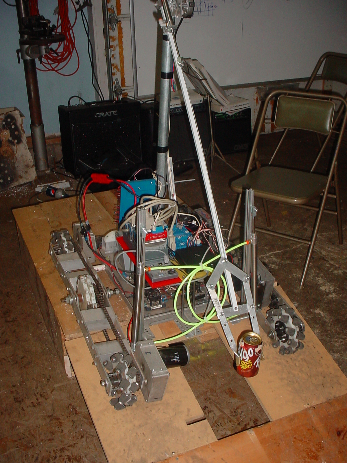
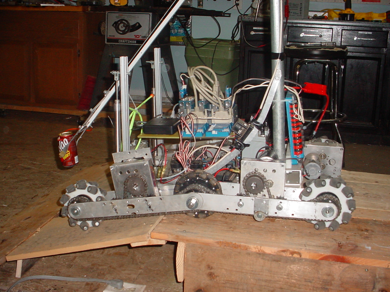
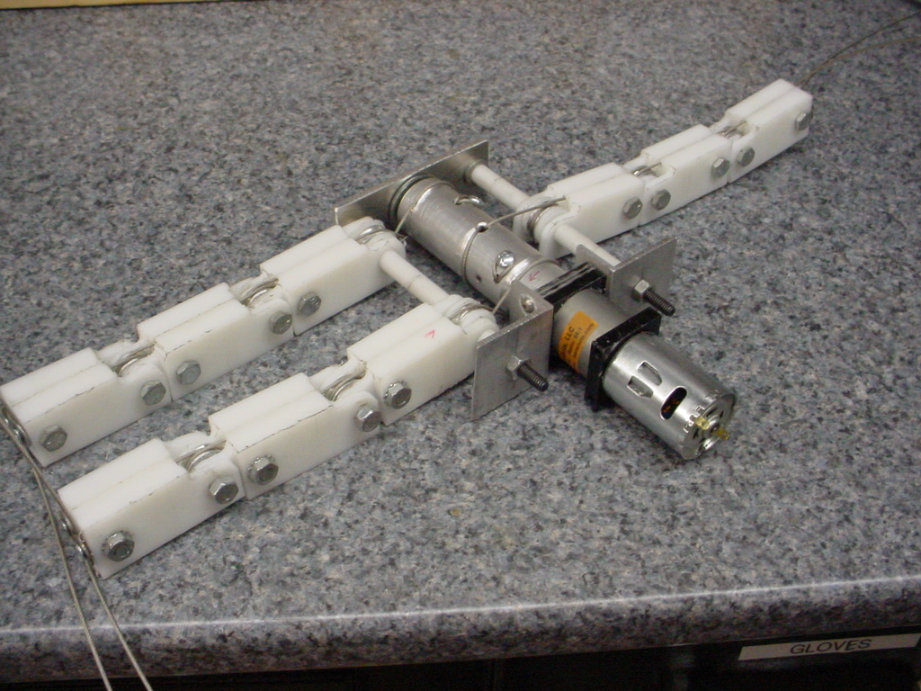
Rotate Drive (CRAB)
Below are a rotating drive system. What will make it work is that the
arm rotates with the drive wheels. So the claw will always be pointing at the
drive direction.
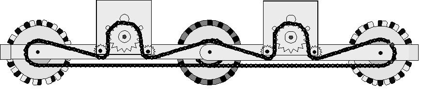
Helical gears are to be used with bearings on each side. Two wheels will help
balance the system. The red indicates the gear housing made in two halves.
A globe motor would be perfect to rotate the direction. One idle gear would
be the drive motor but both would tension the chain. You could actually put the
chains inside tubes to hide them and also support the robot.
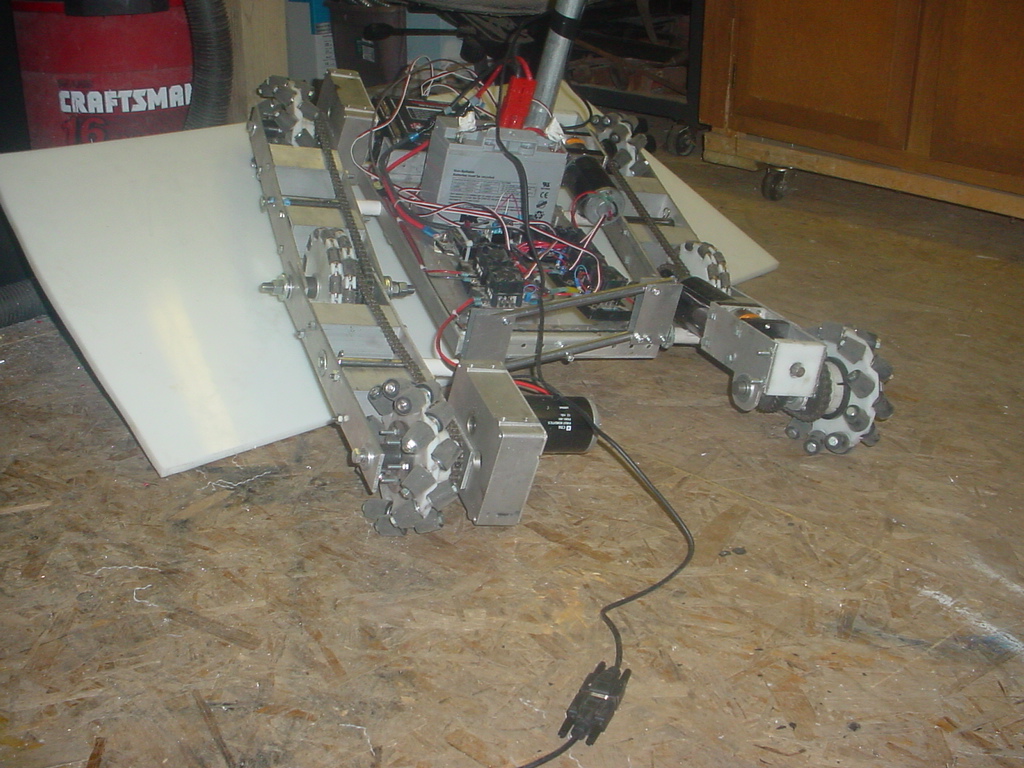
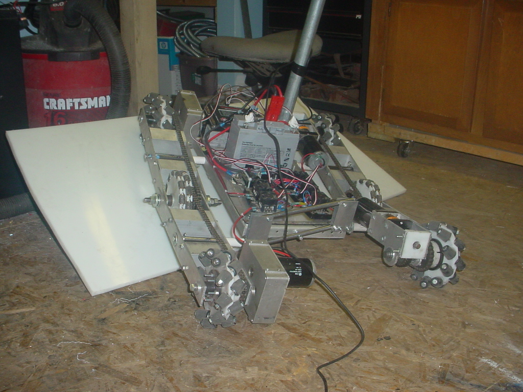
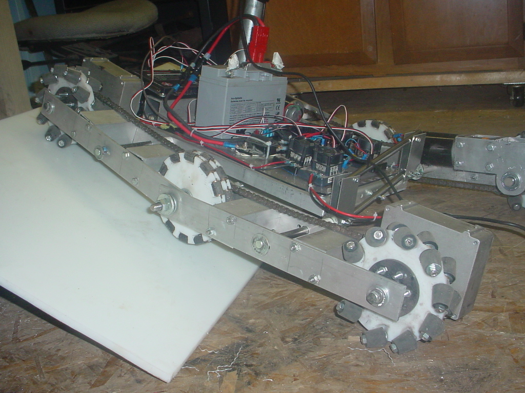
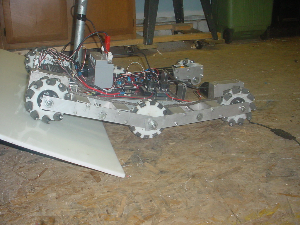
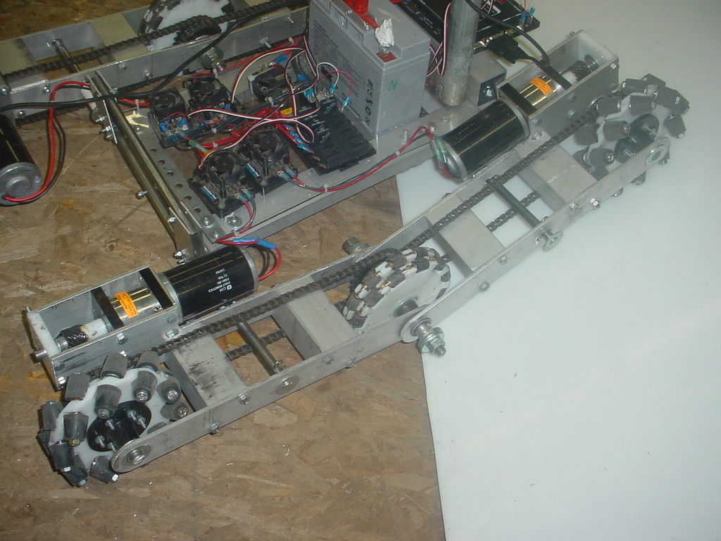
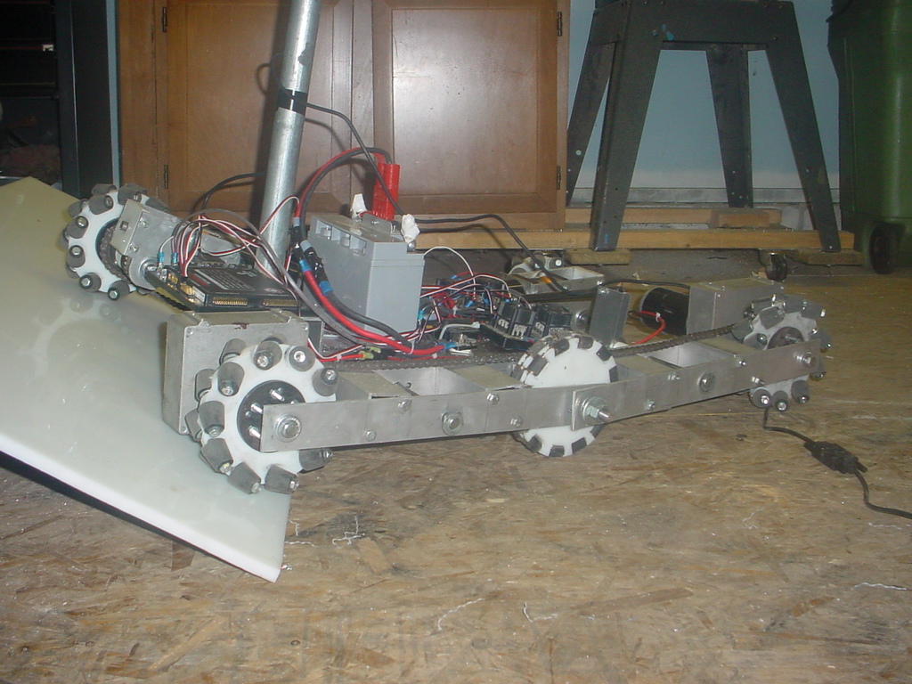
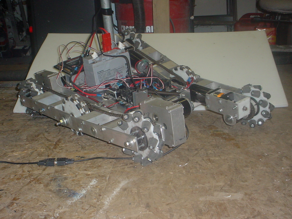
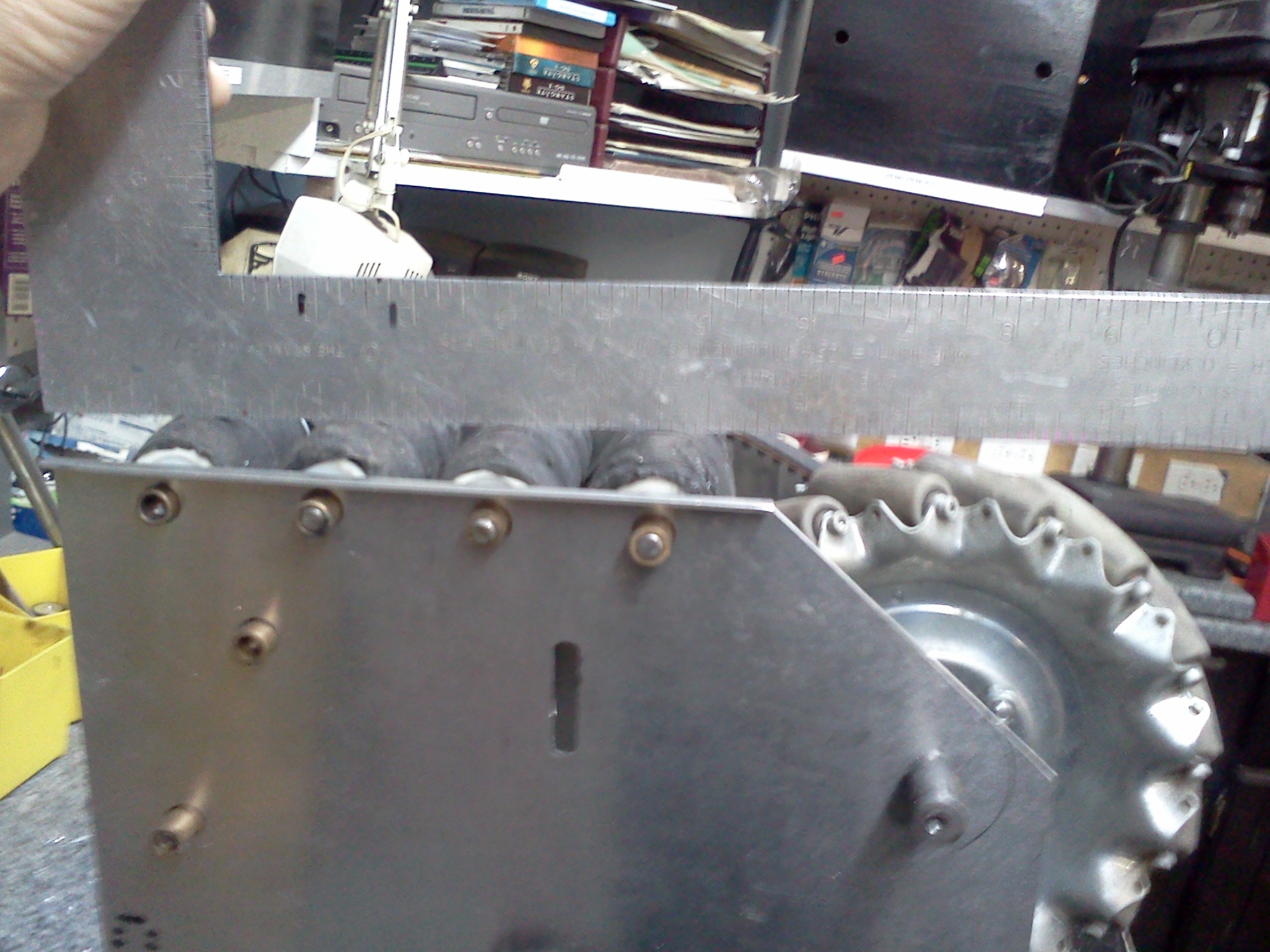
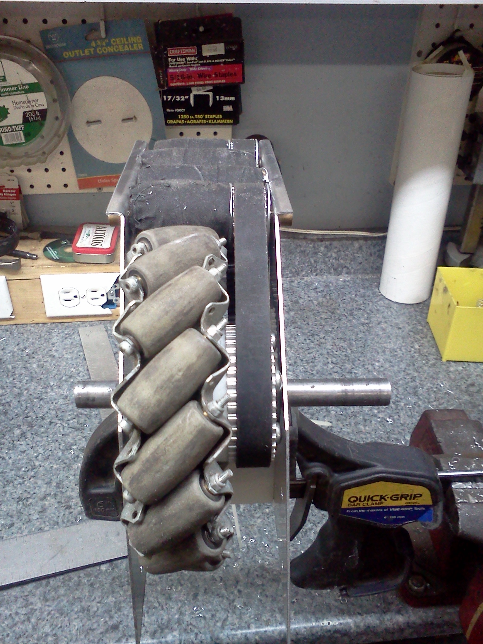
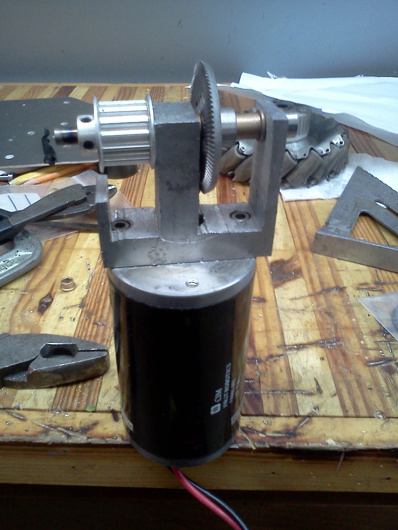
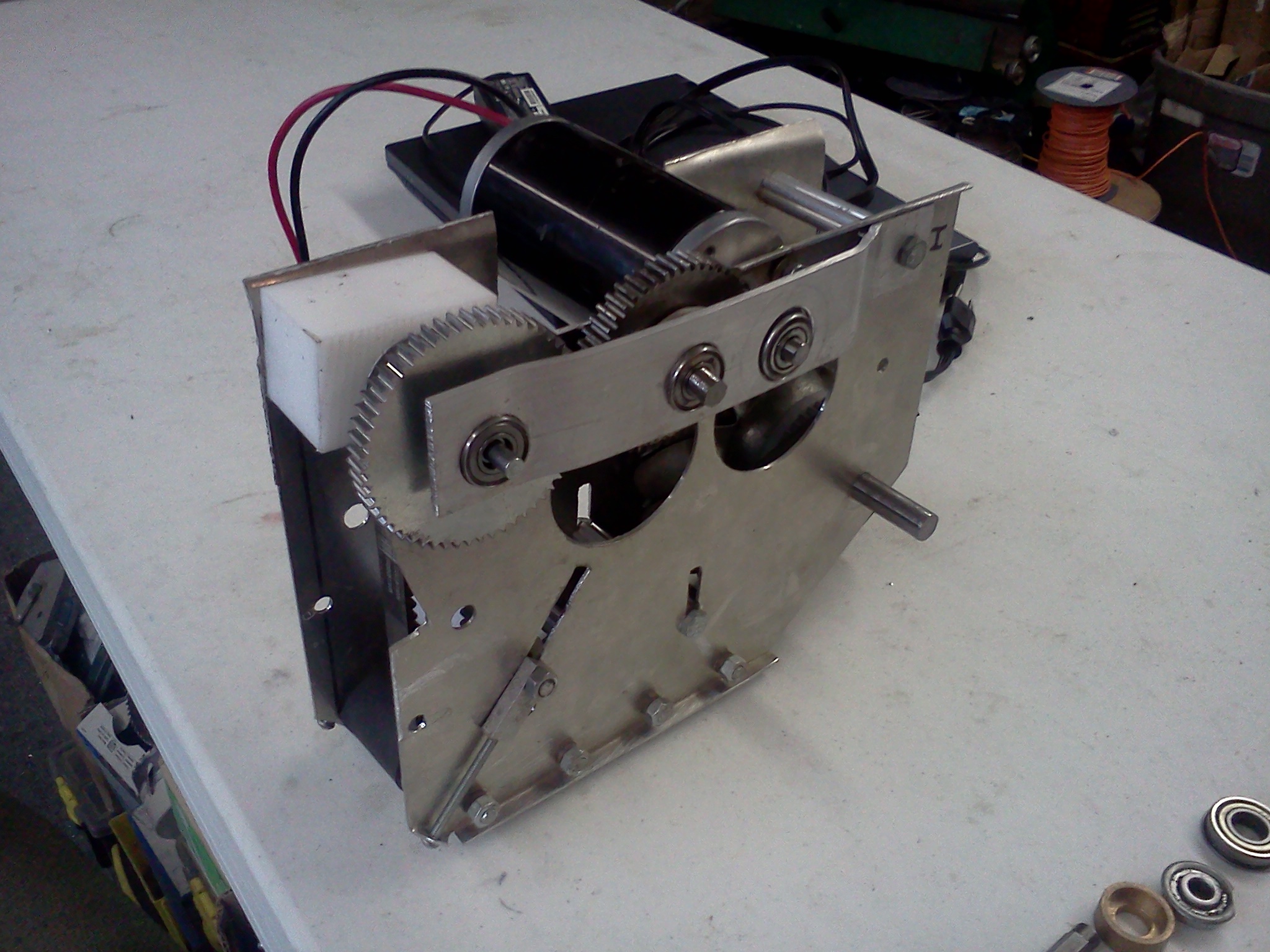
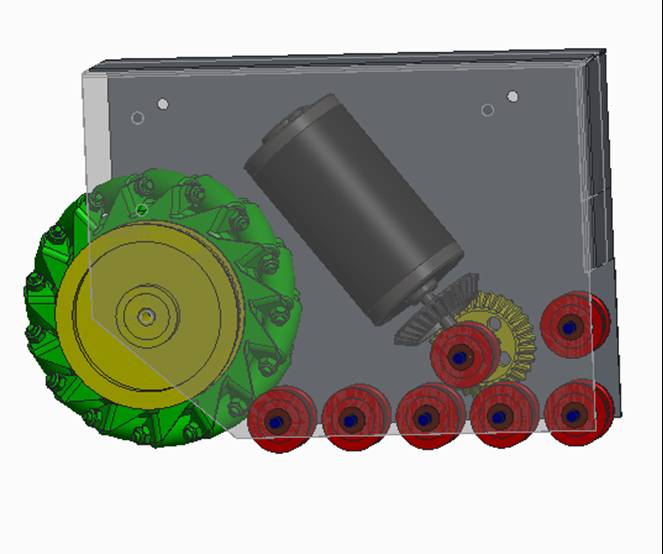
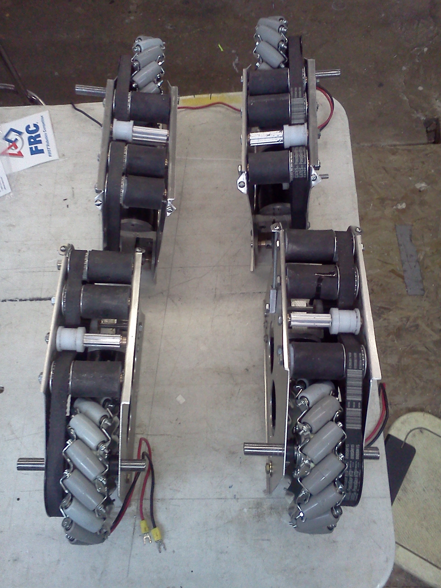
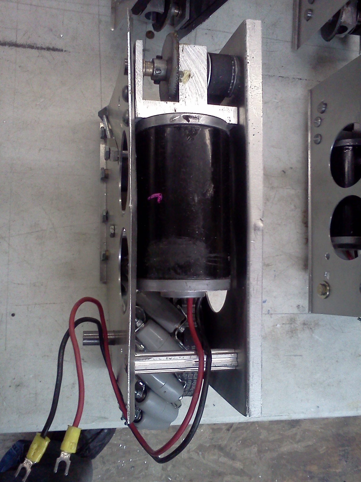
All
Wheels Drive
All drive: This Idea has a lot of potential but is unsolved. The Idea is to
have one CIM motor run a corner section of the wheels (2 x 24 = 48) and those
wheels can turn 360 degrees. The turn motor would be connected with four
flexible shafts. The wheels block is also on a suspension allowing it to tip
enough to go up ramps. With Four wheel blocks that would be a total of 4 x
48 = 92 wheels. This would be fast, strong, and maneuverable.
Above, driving an angle direction.
Variable Worm Gear
Above is a worm gear with a curve shape. Along the curve is a idler
gear attached to an arm that can move it along the curve. The larger gear is the
drive gear attached to a shaft for power for drive wheels. At this time we
do not have the capability to produce this worm gear.
Kicker
The above kicker was found to be very effective and easy to build. You can
hook a vex motor to a variable relief valve and very the kick distance very
well.
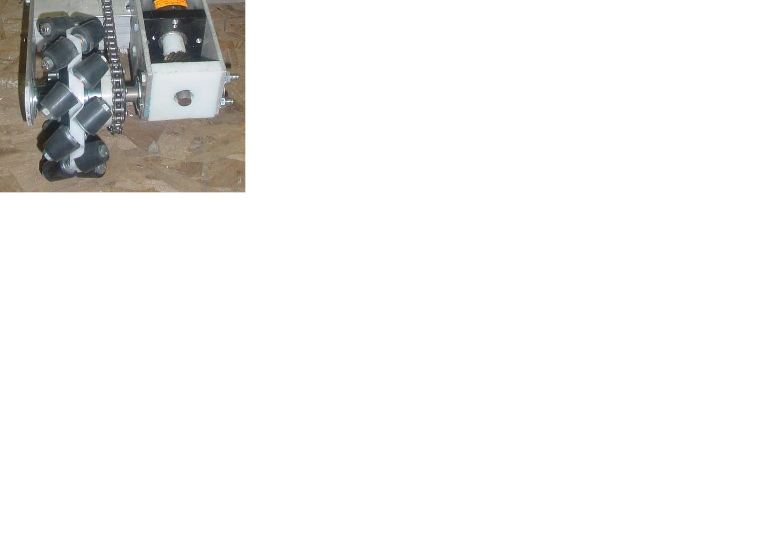
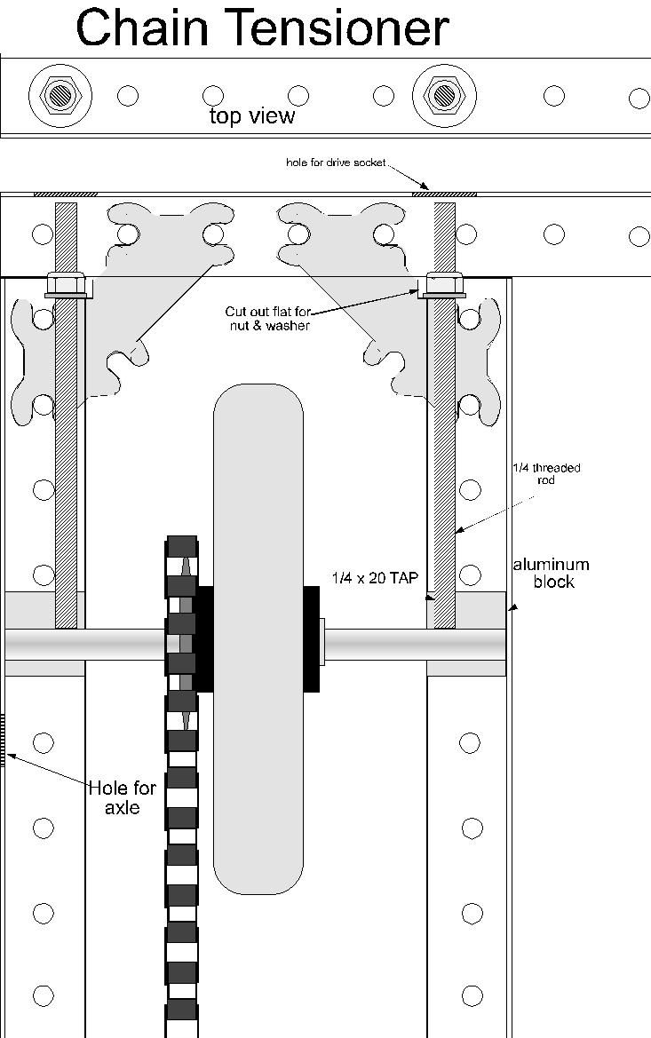
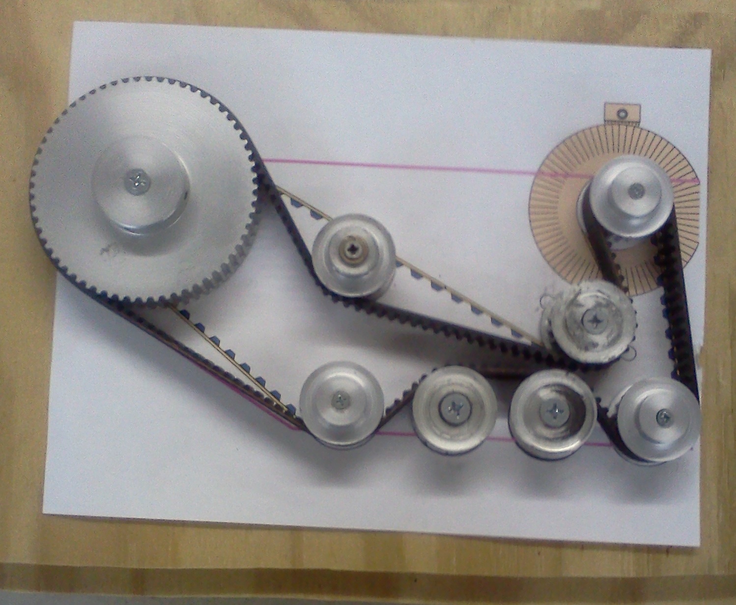
Chain Tensioning
The above idea has worked very well for us and is easy to build.
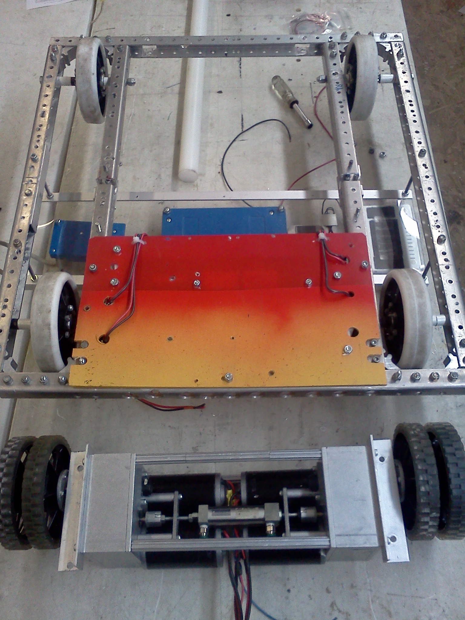
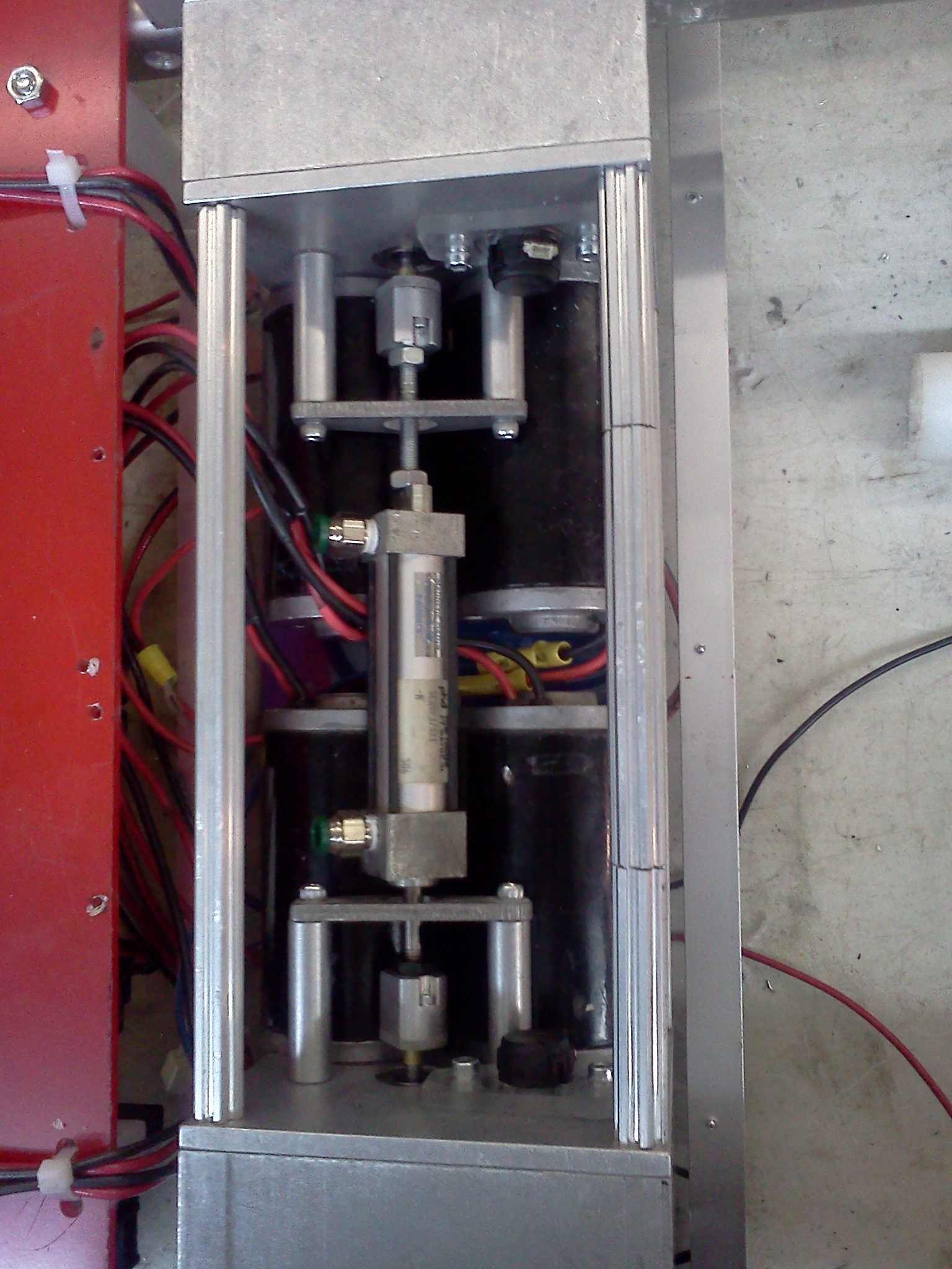
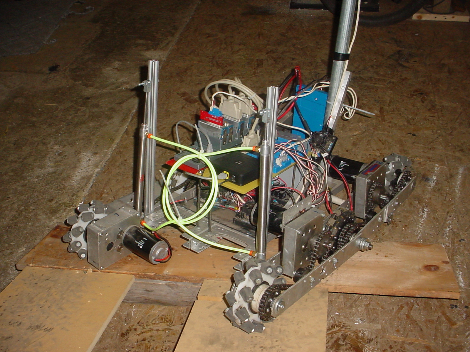
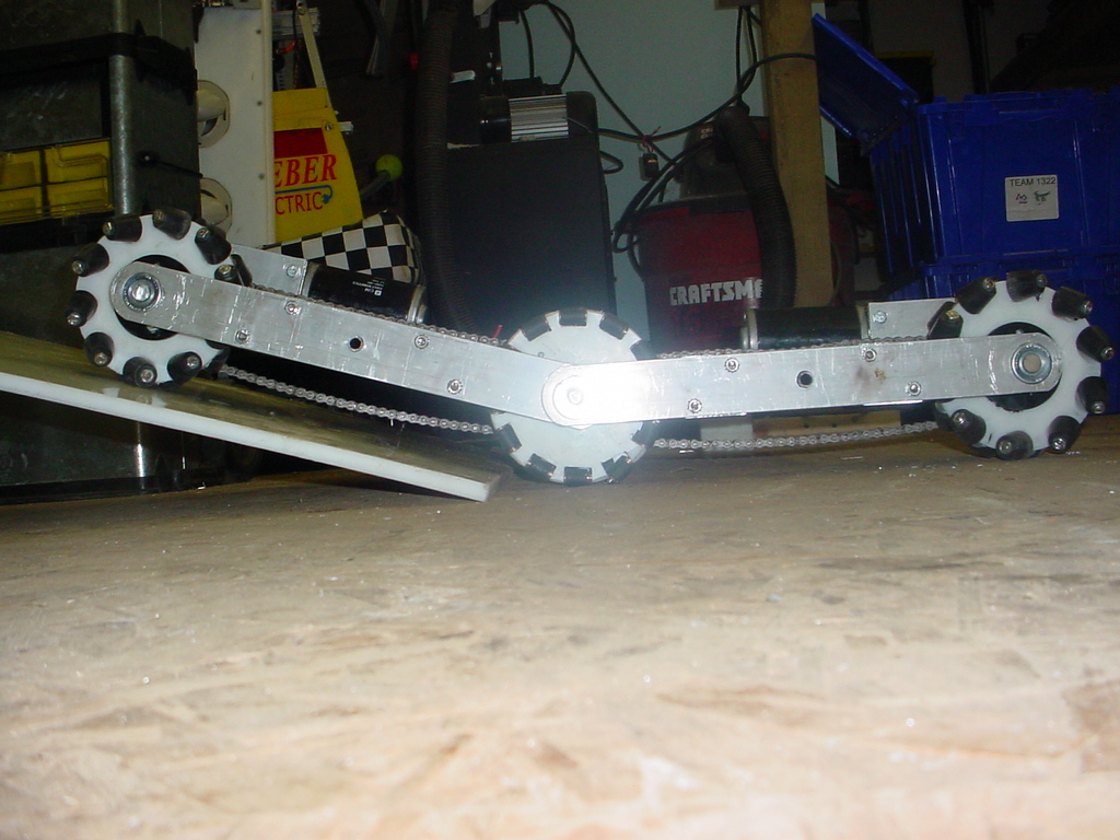
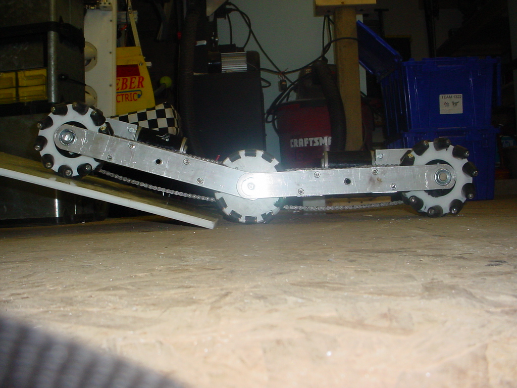
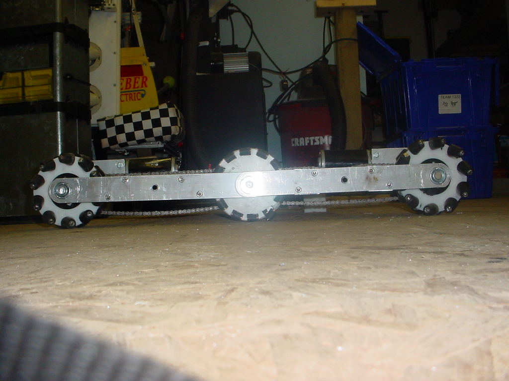
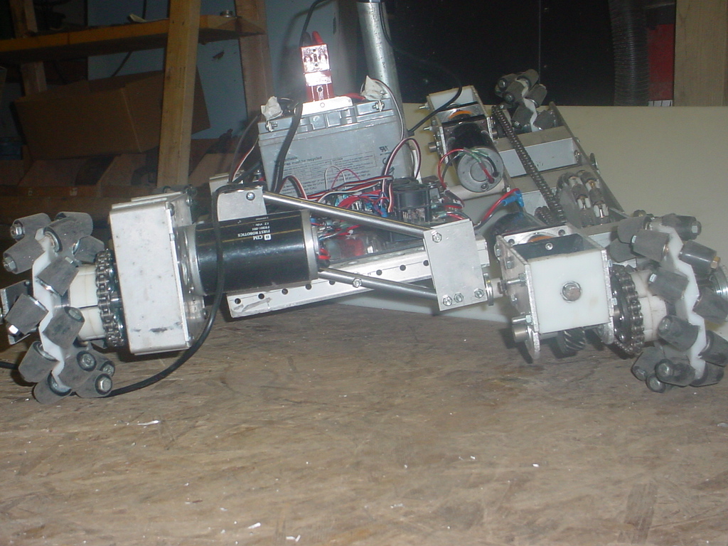
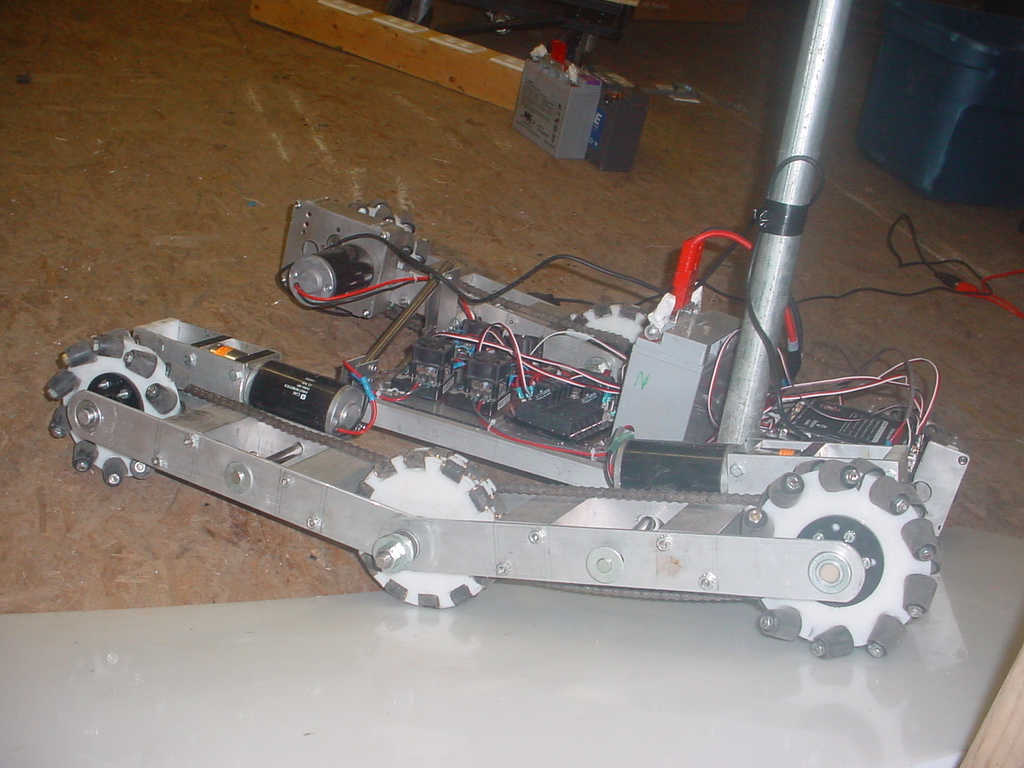
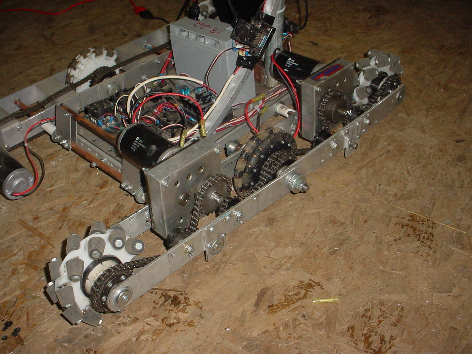
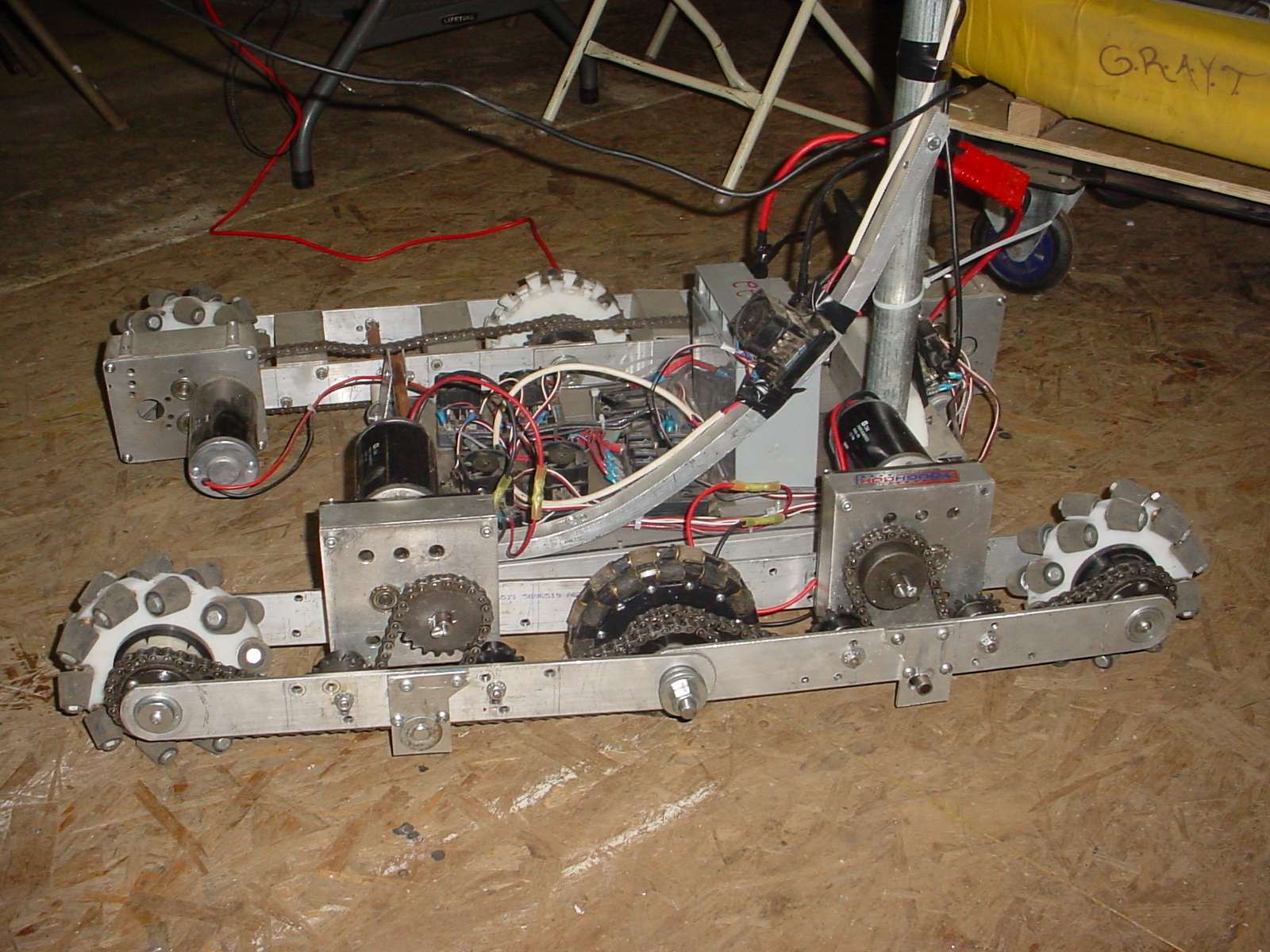
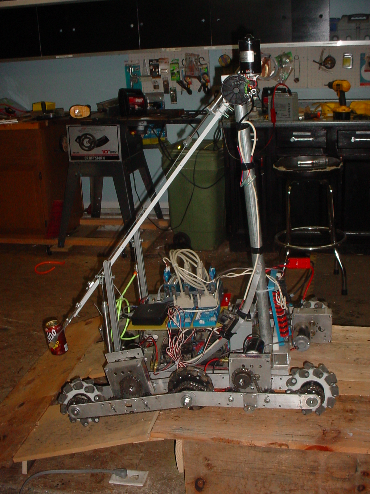
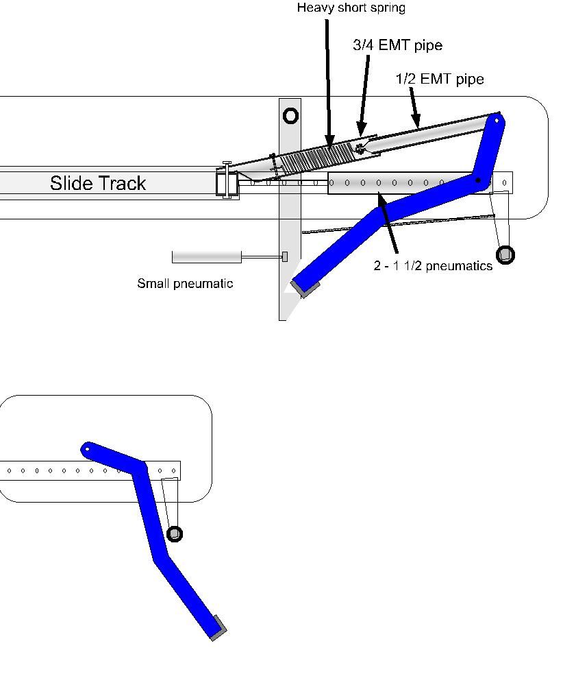
Drop Drives
We developed a drop drive system, our hope was to use
the belt that drives the wheels to also run along the
floor which would be double duty for the belts. We used
pneumatics to drop the drives and with the smaller
wheels making contact with the floor this would give an
automatic reduction giving us pushing power. After
assembly and use we found that one CIM was not enough
power to reach the top speed needed for game play. we
would have to add one motor to each of the drives to
make useful.
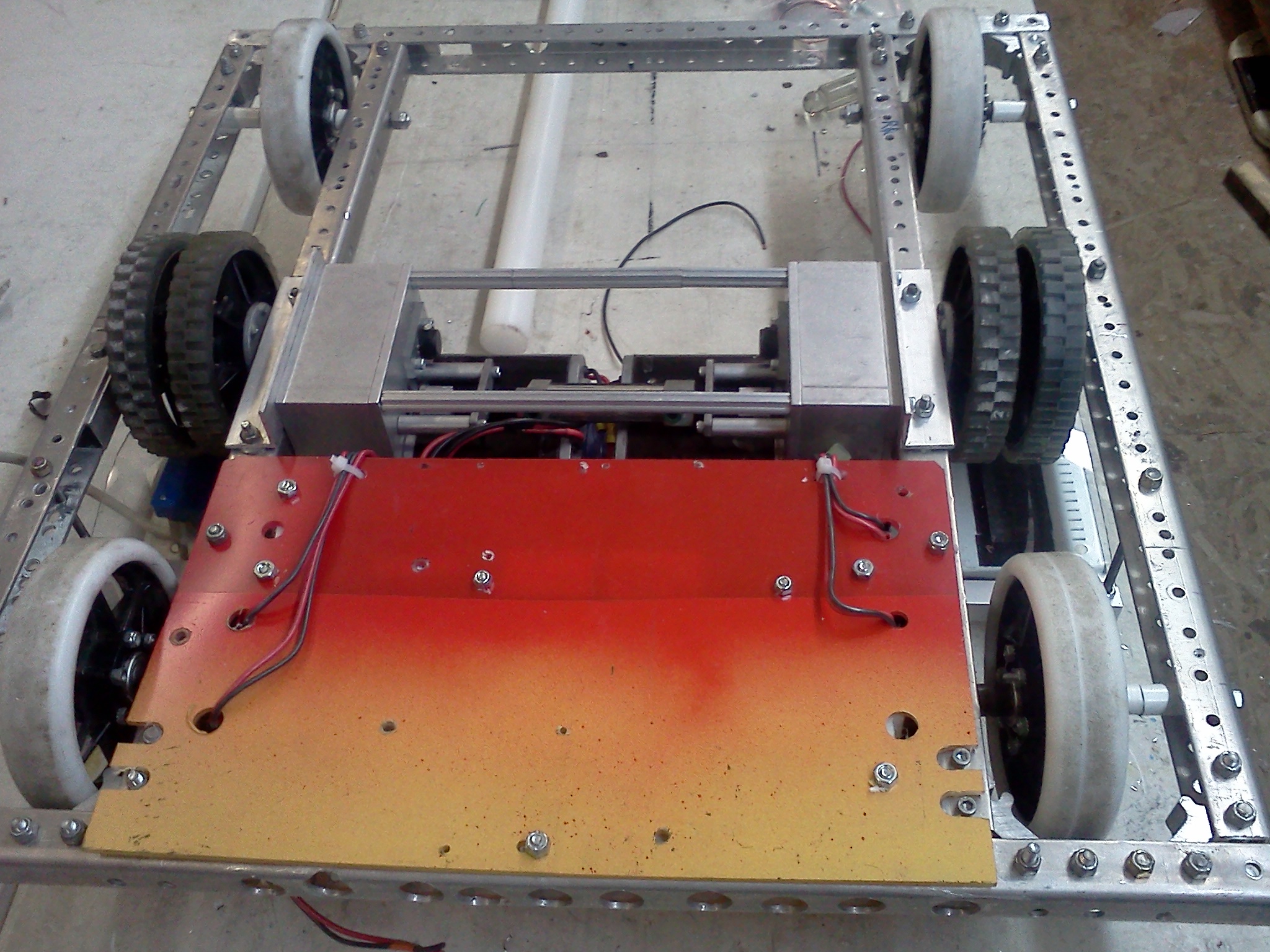
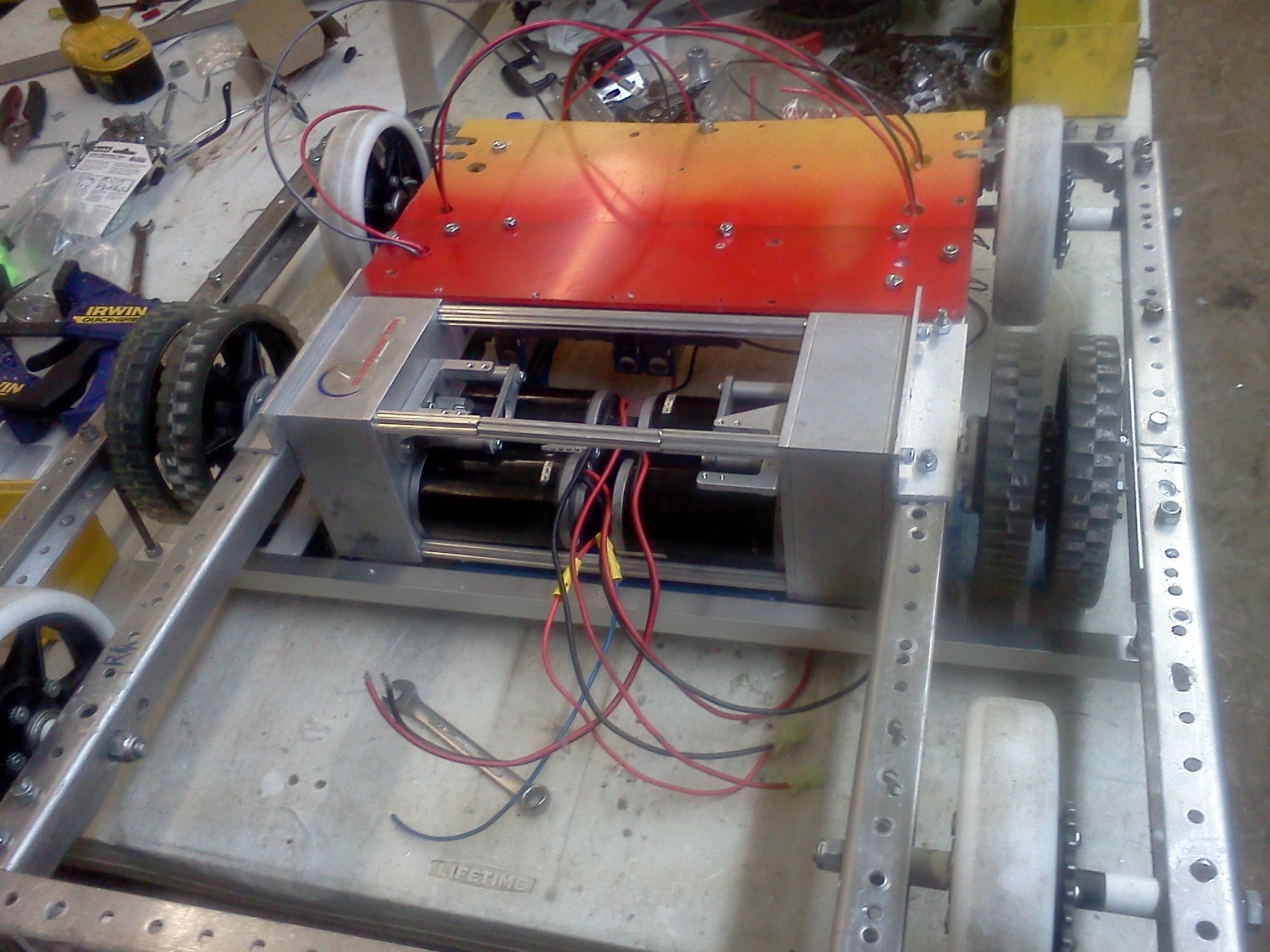
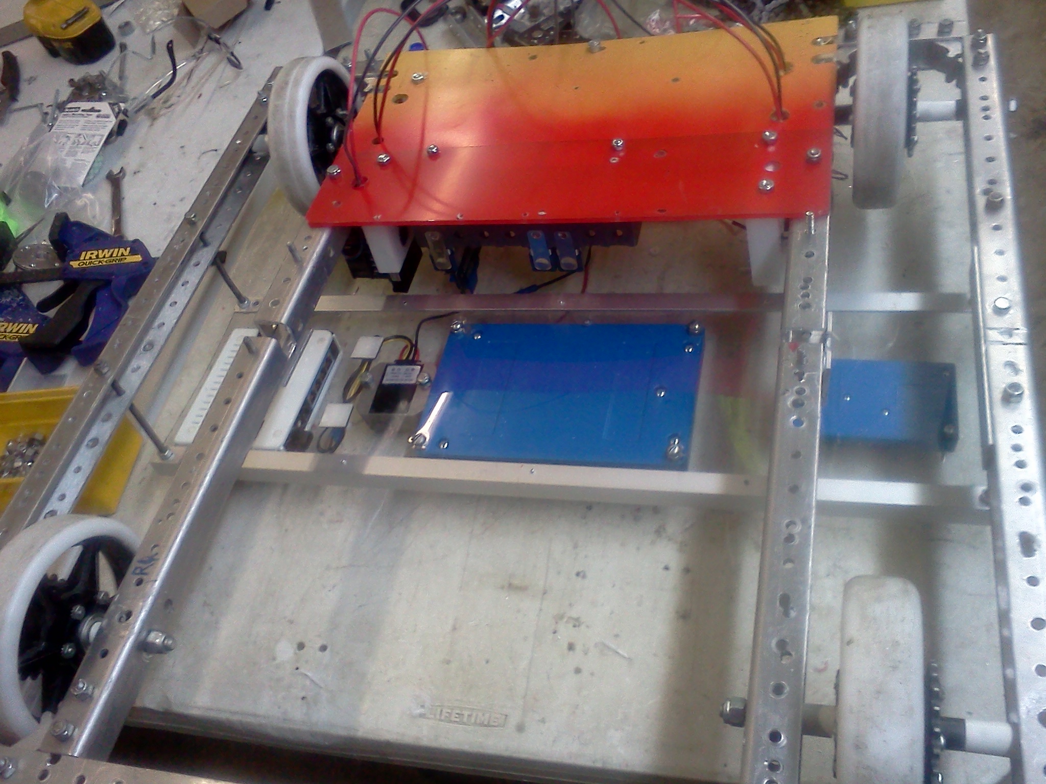
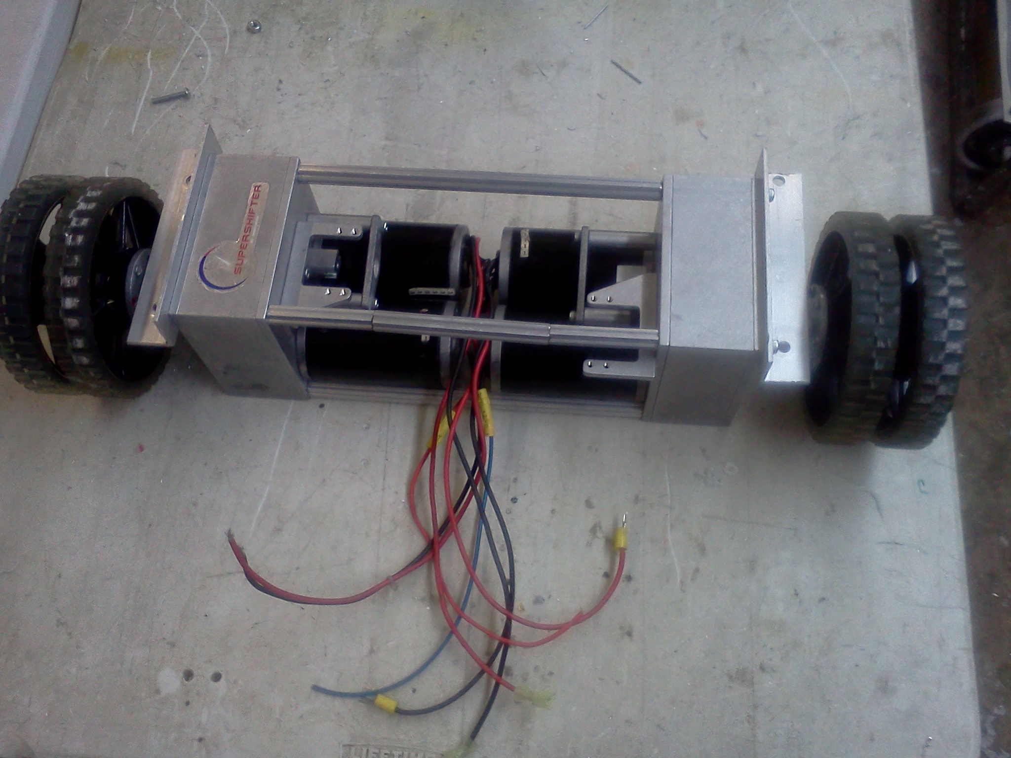
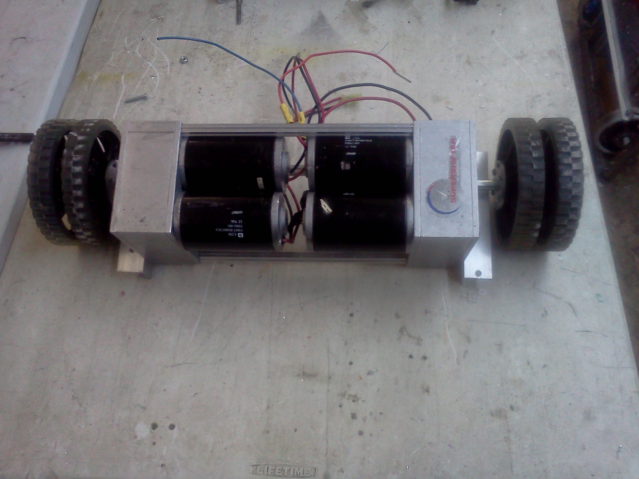
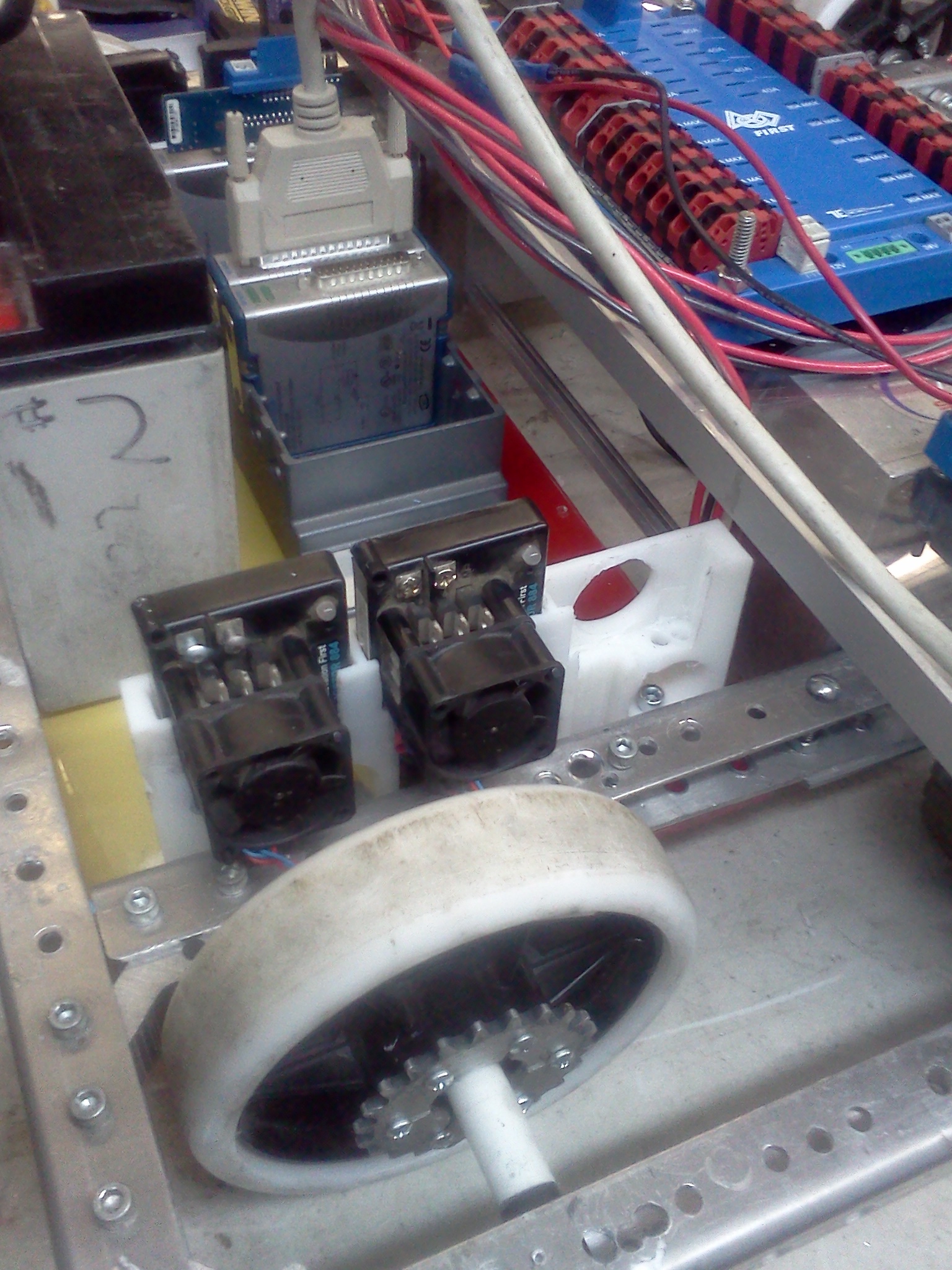
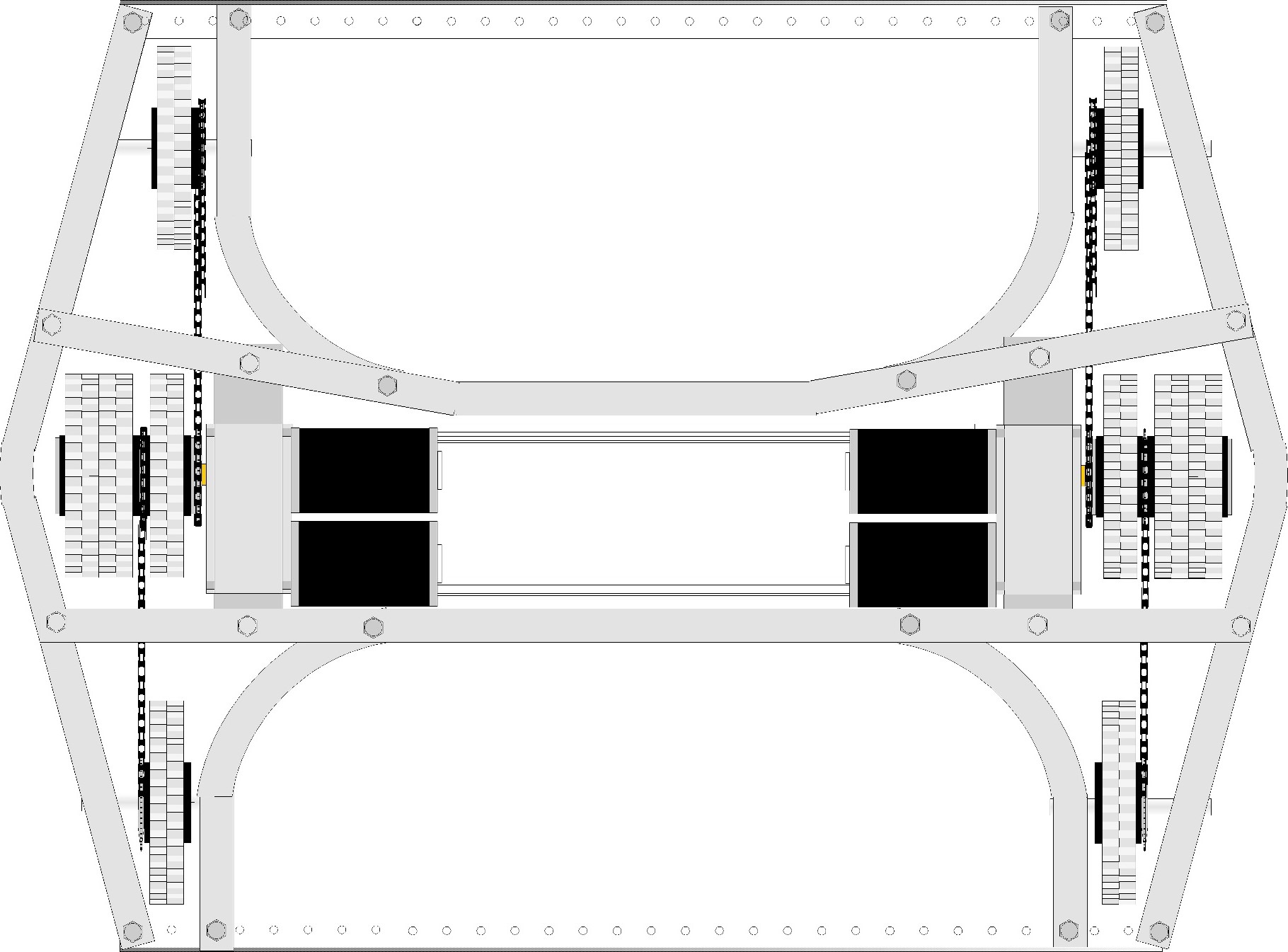
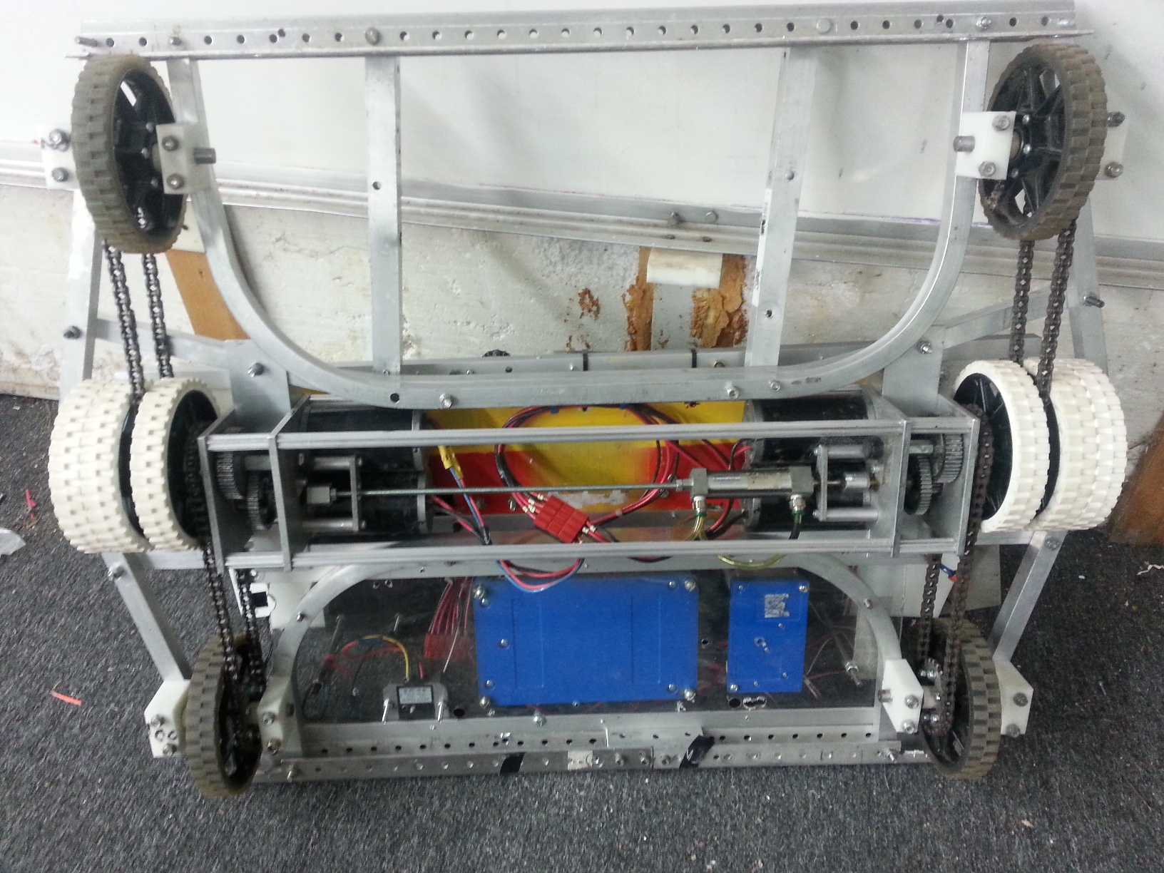
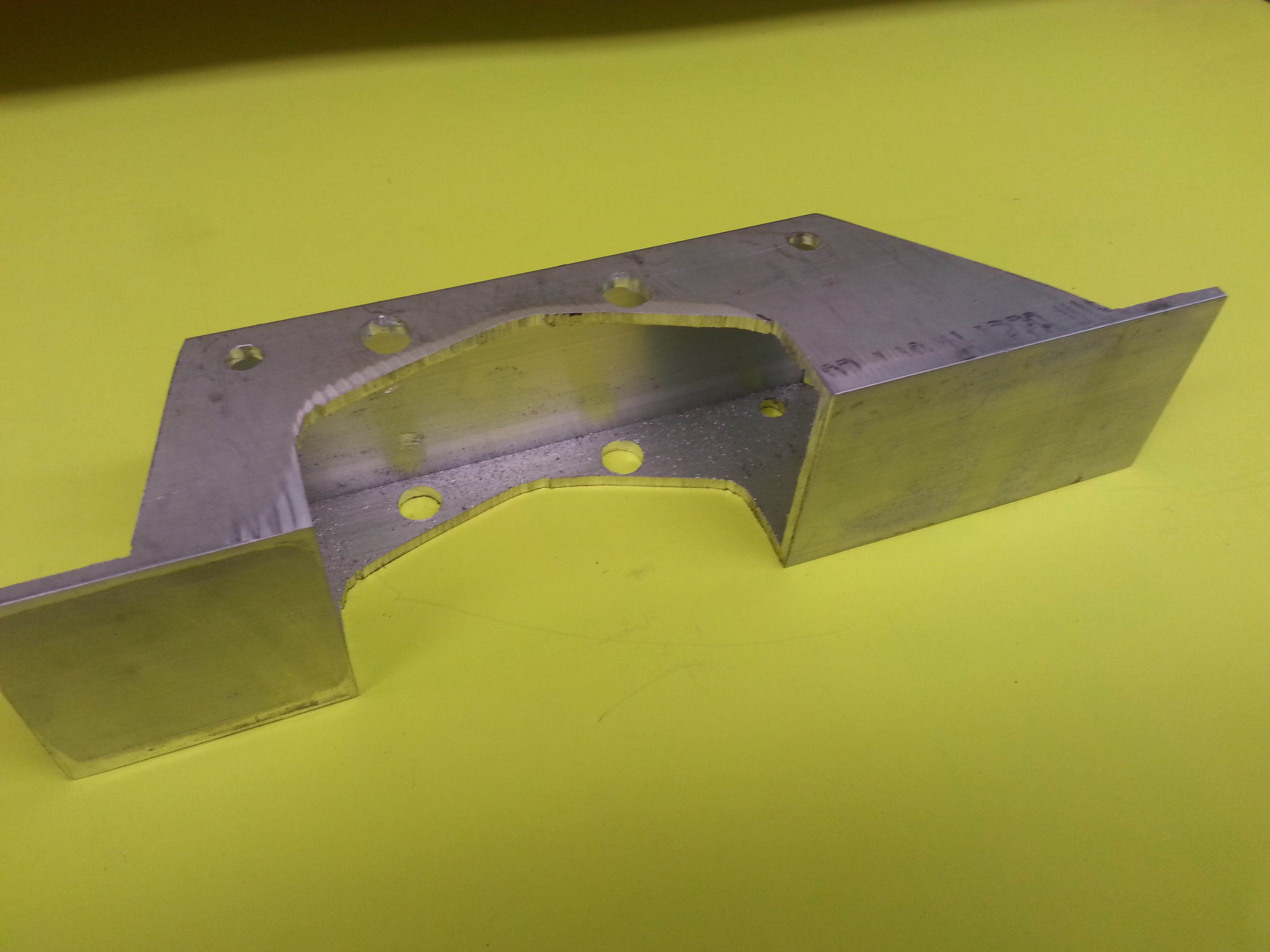
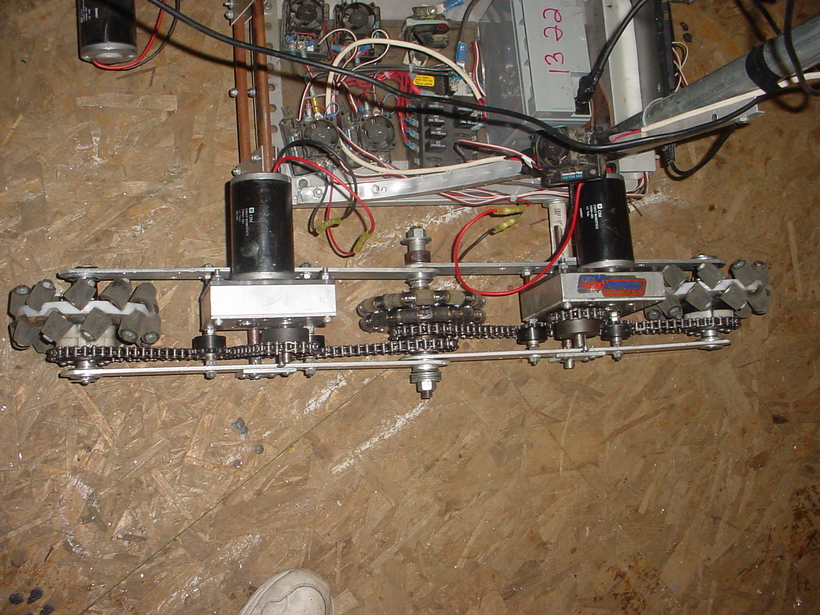
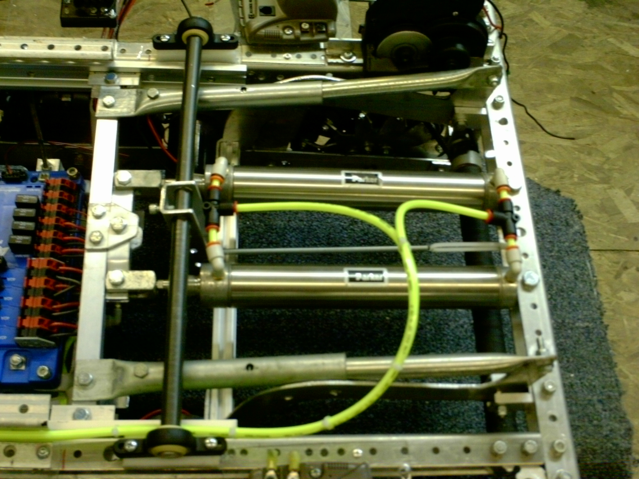
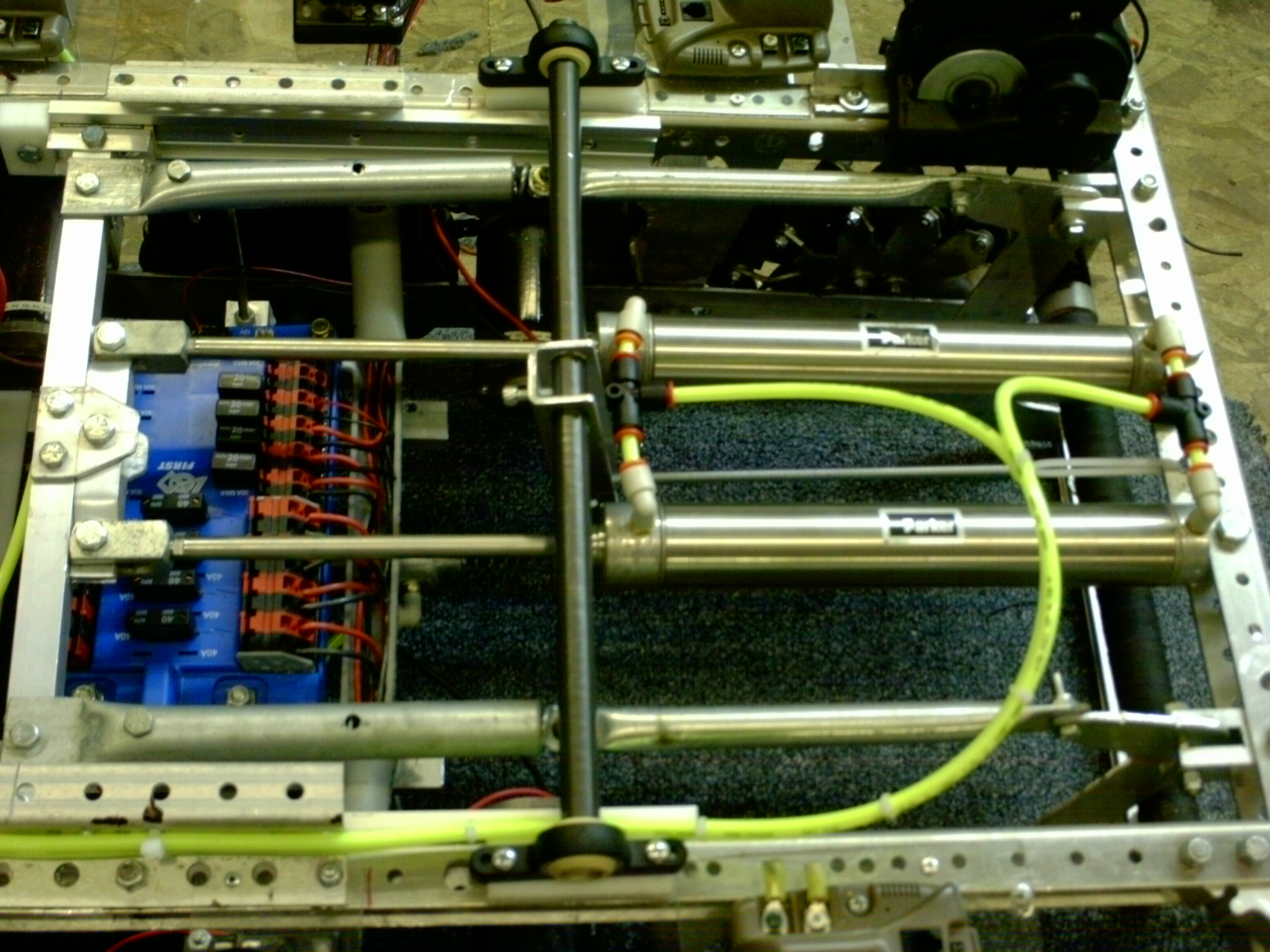
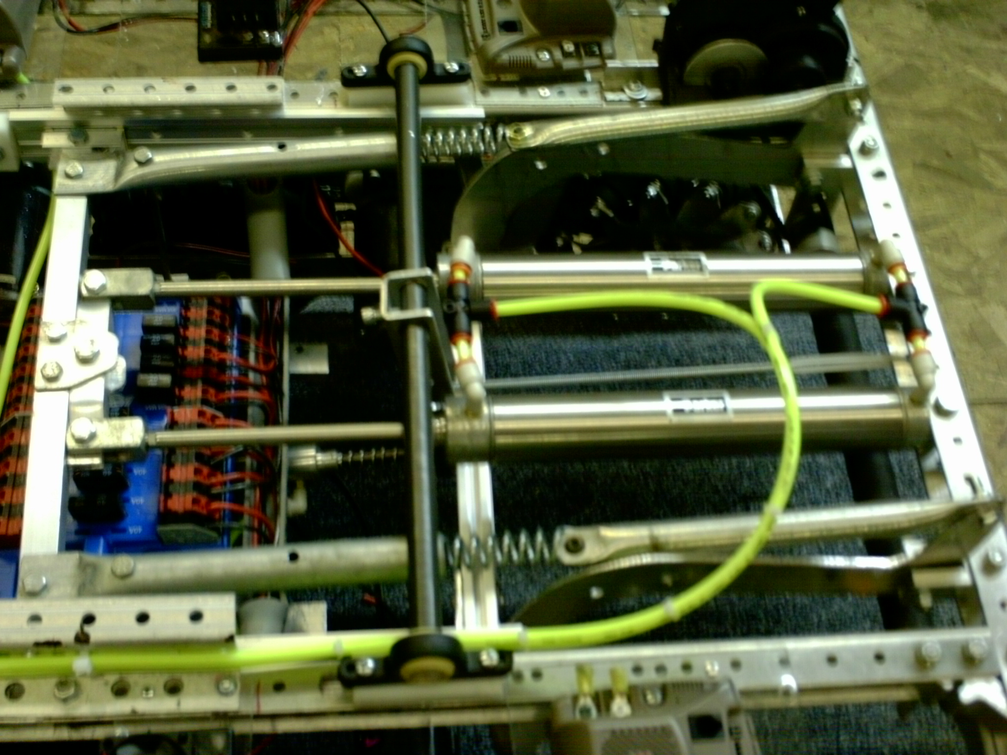
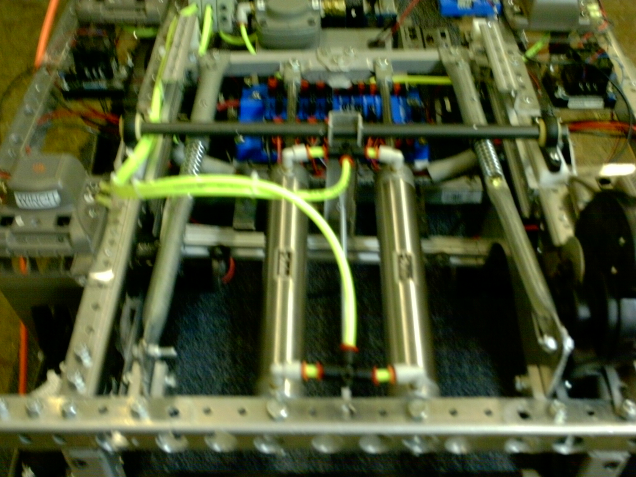
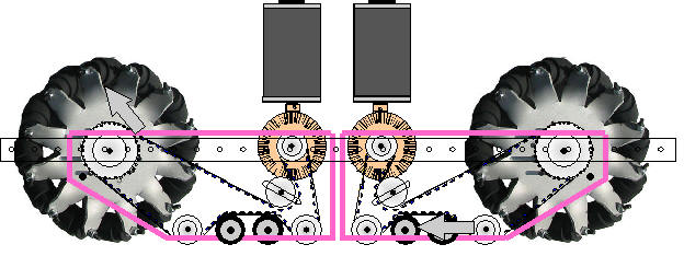
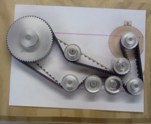
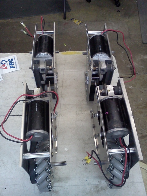
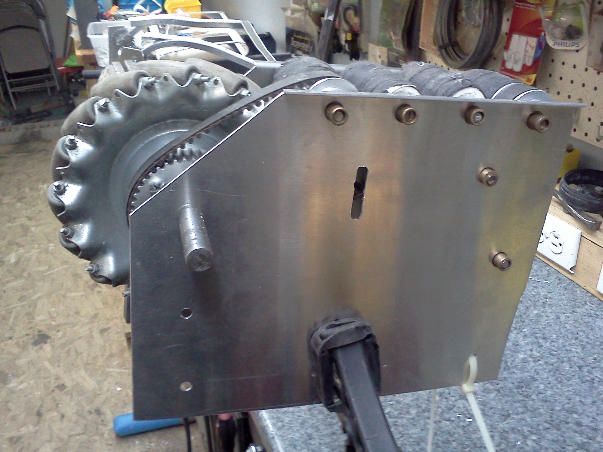
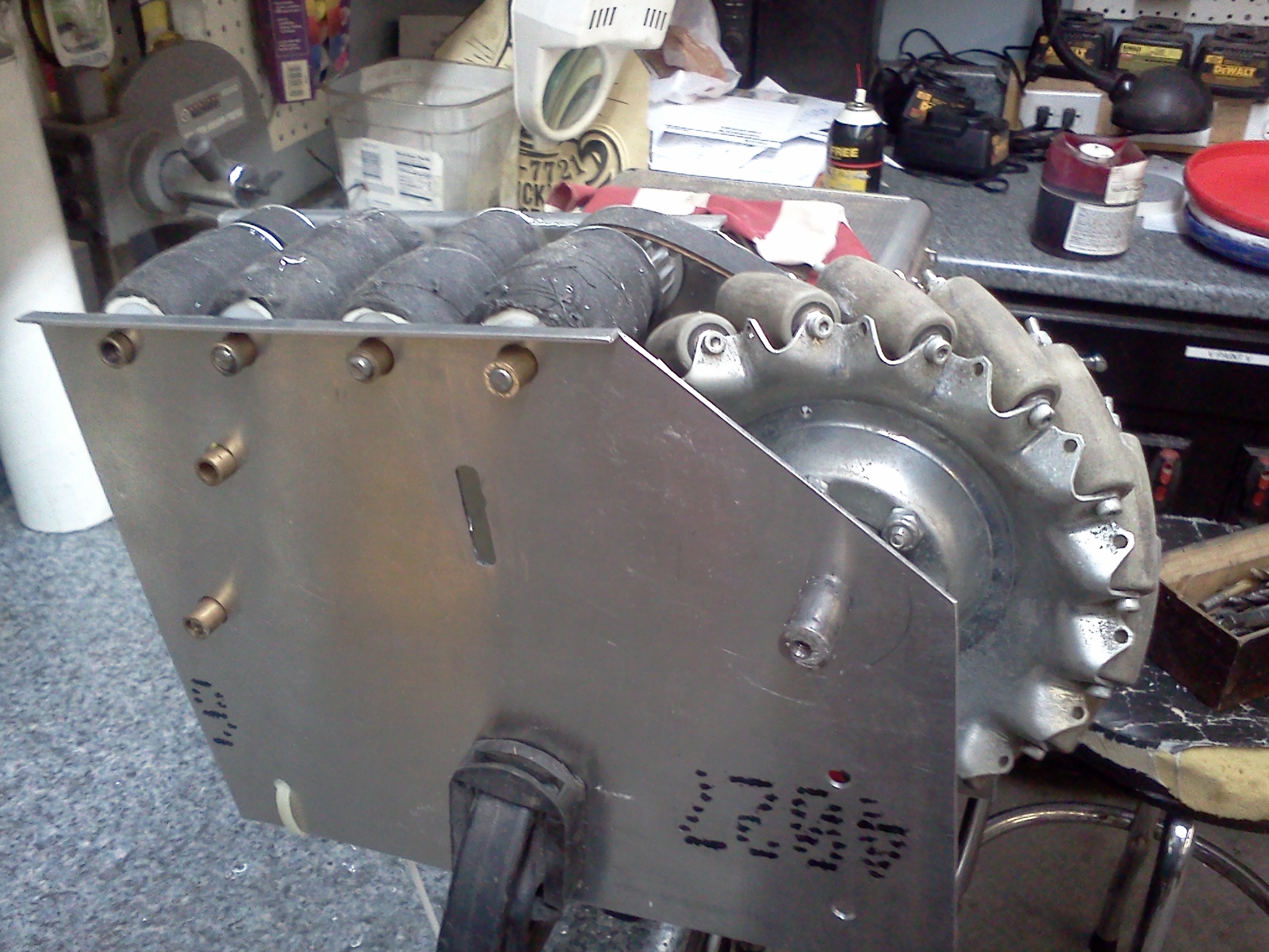
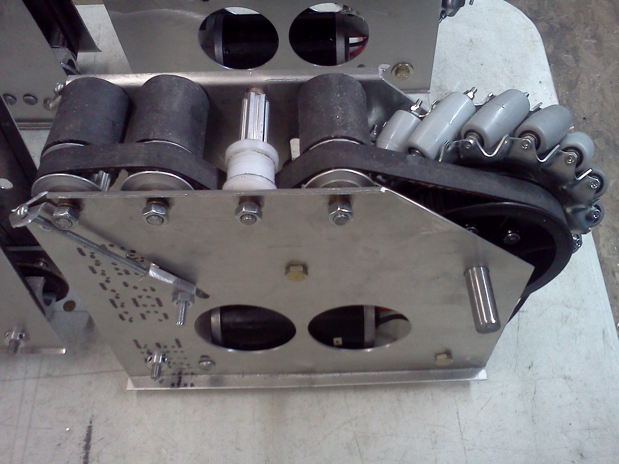
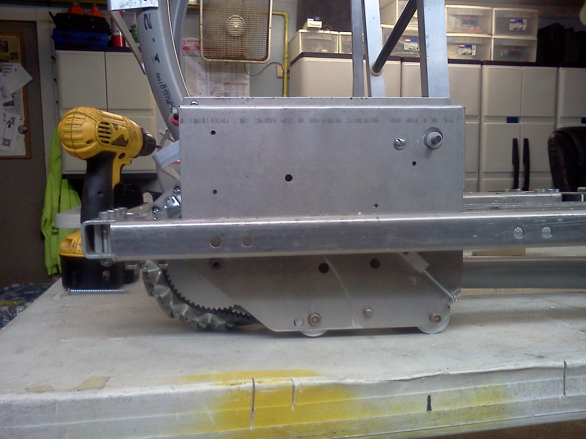
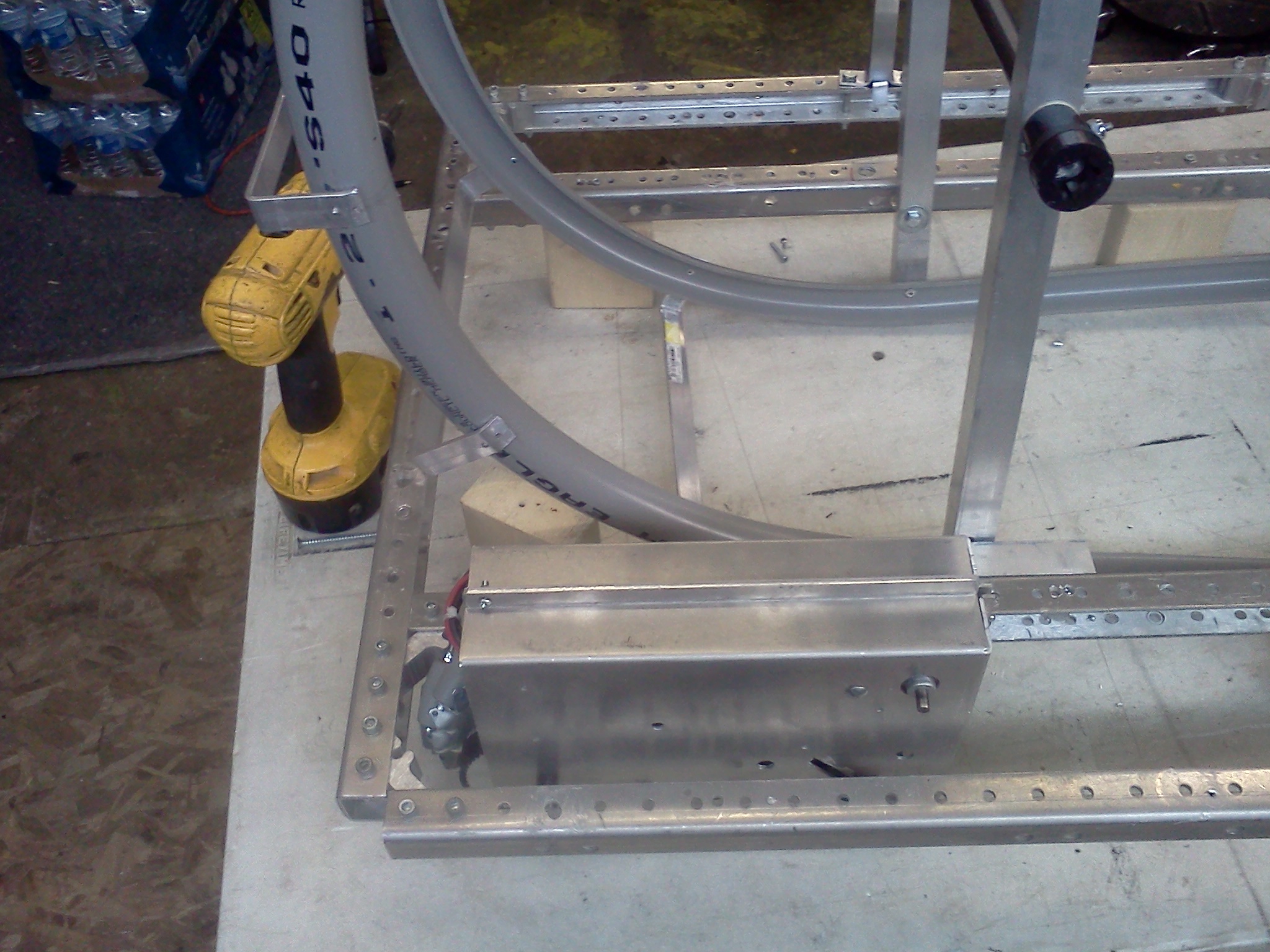
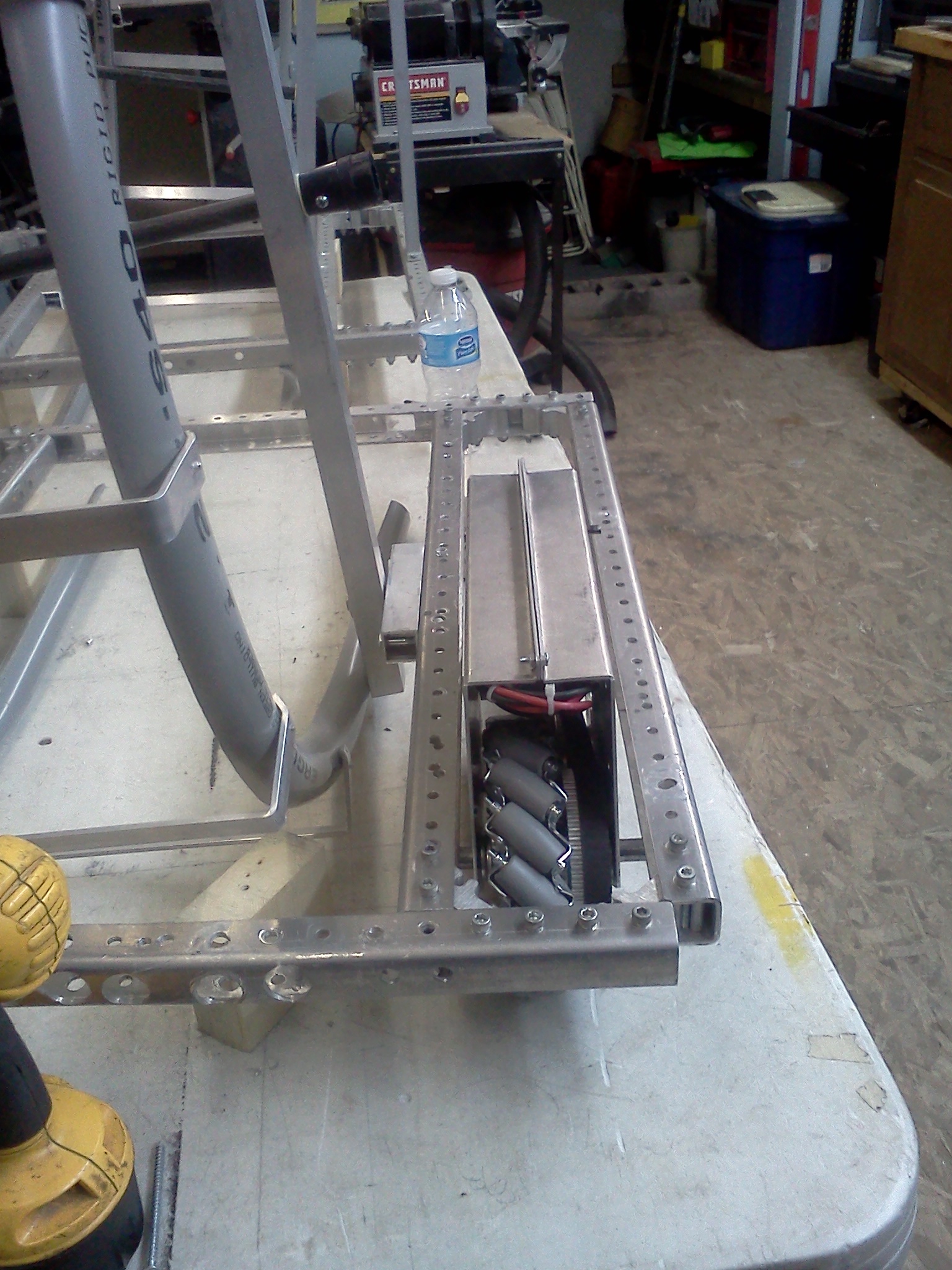
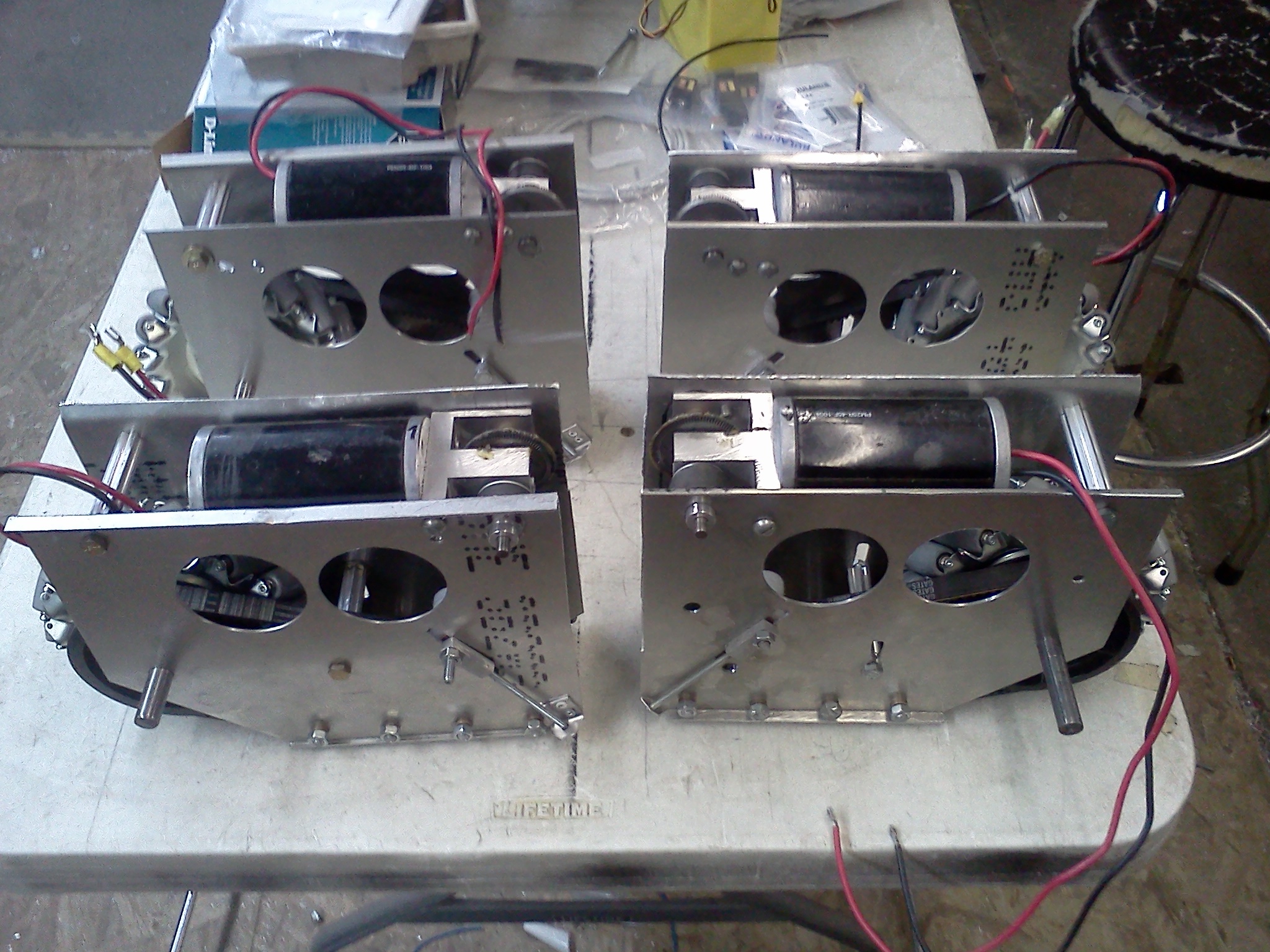
Modular Drive
To get away from
prototyping new drives we decided to test a modular
drive system that we can use from year to year. We
purchased two super shifters from
Andymark and
assembled them into a module. We took on gear box and
flipped the plate so they could be assembled in a mirror
of the other one and connected them. doing this allowed
us to use one pneumatic cylinder to shift them
instead of two. To make it fit in the frame we had to
flush mount some of the screws and attach 1 1/4 inch
aluminum angle for a connection support. We had to cut a
slot into the frame that would allow the axle of the
gear boxes to be center of the frame to match the other
wheels. This version will be a six wheel drive connected
with chains and installing different size washers we
could drop the center wheels the amount needed to help
with turning. All four motors are connected with
Anderson connectors into one module allowing us to
quickly remove the whole drive module with first
removing four nuts and than unplugging the Anderson
connector block. Once removed it is easy to remove a
rive motor and un plug in from the Anderson connector
block.
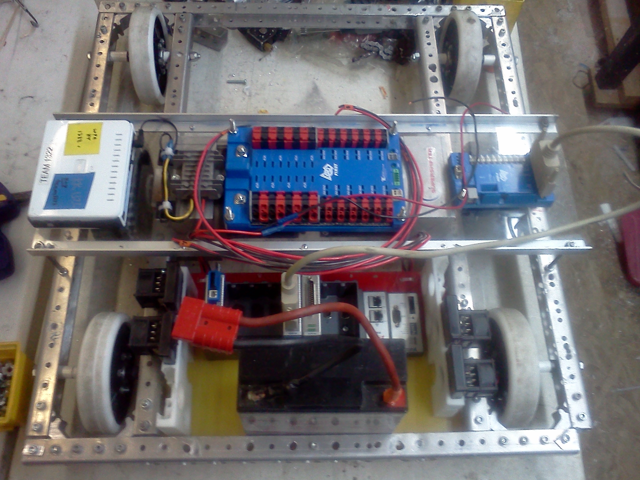
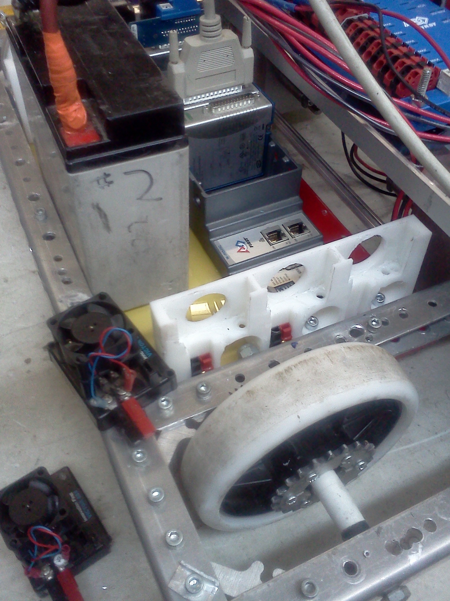
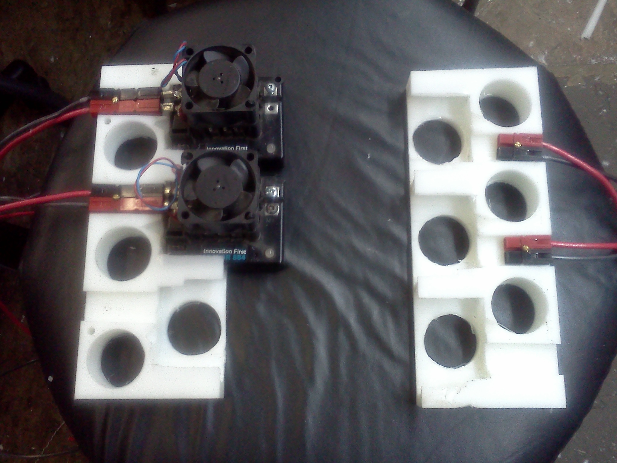
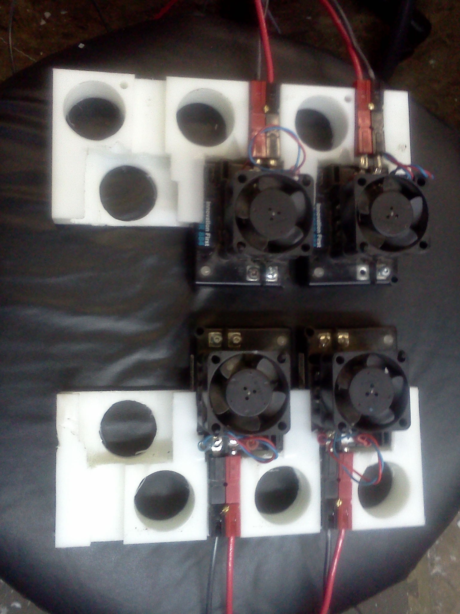
Quick Connect Victor
Base
We have developed a base that you can plug in a
Victor 884 speed controller into. Using this base allows
for quick and easy installation and removal of the
Victors. We also found that installing the Victors on
end allowed the Victors to fit in a smaller space. We
attached Anderson connectors to loop terminal connectors
and connected them to the Victor speed controller. To
connect wires just unplug the Victor, attach the wires
and then plug it back into the base. Fast and easy. The
base is a thick piece of HDPE that we cut to fit the
Victor speed controller. In our original design we
allowed for a set of three Victors in each base and may
change that as we learn more about it.
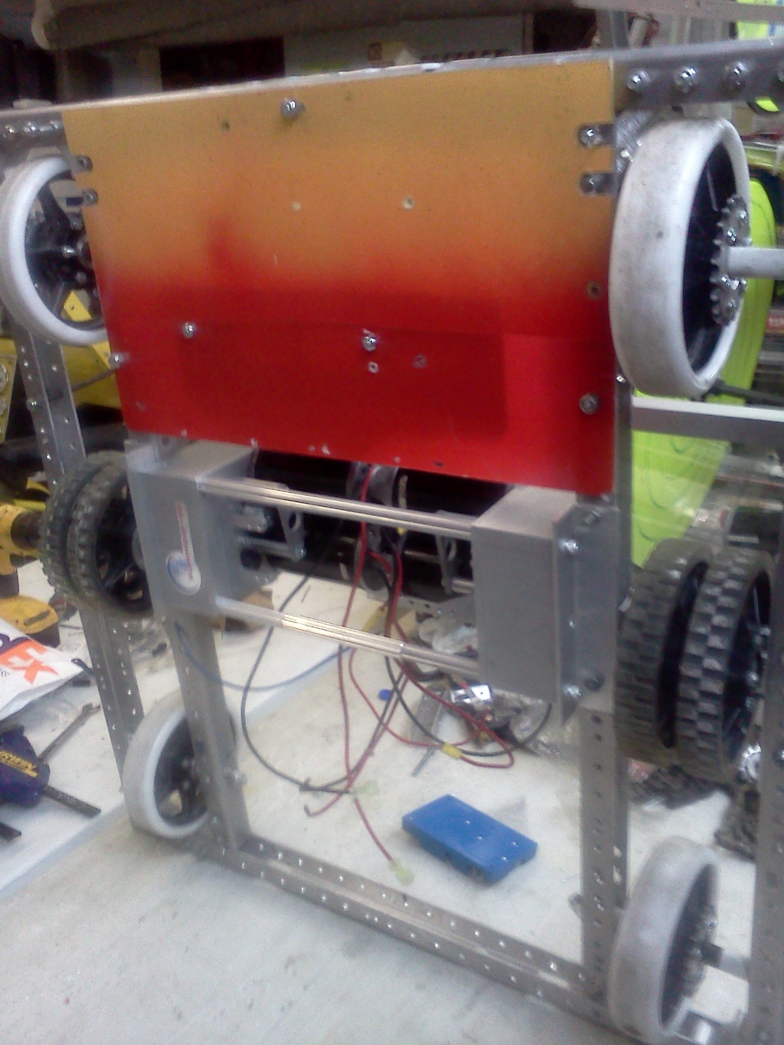
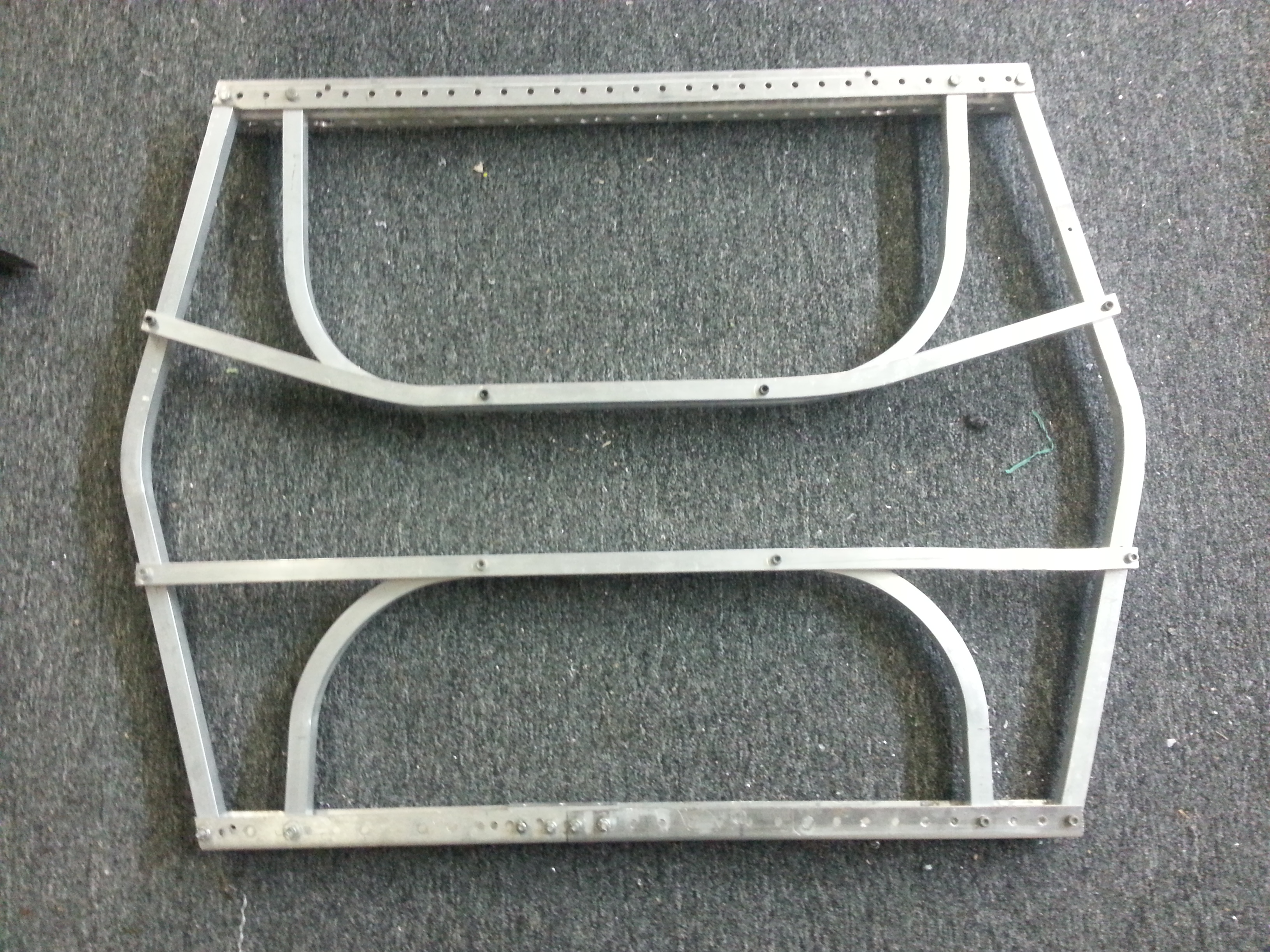
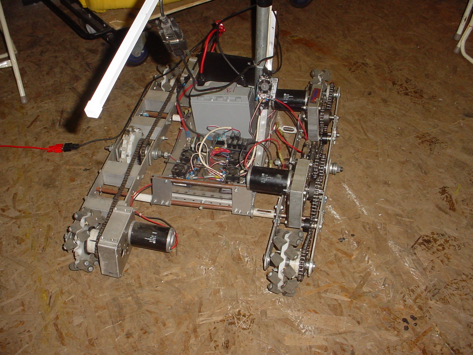
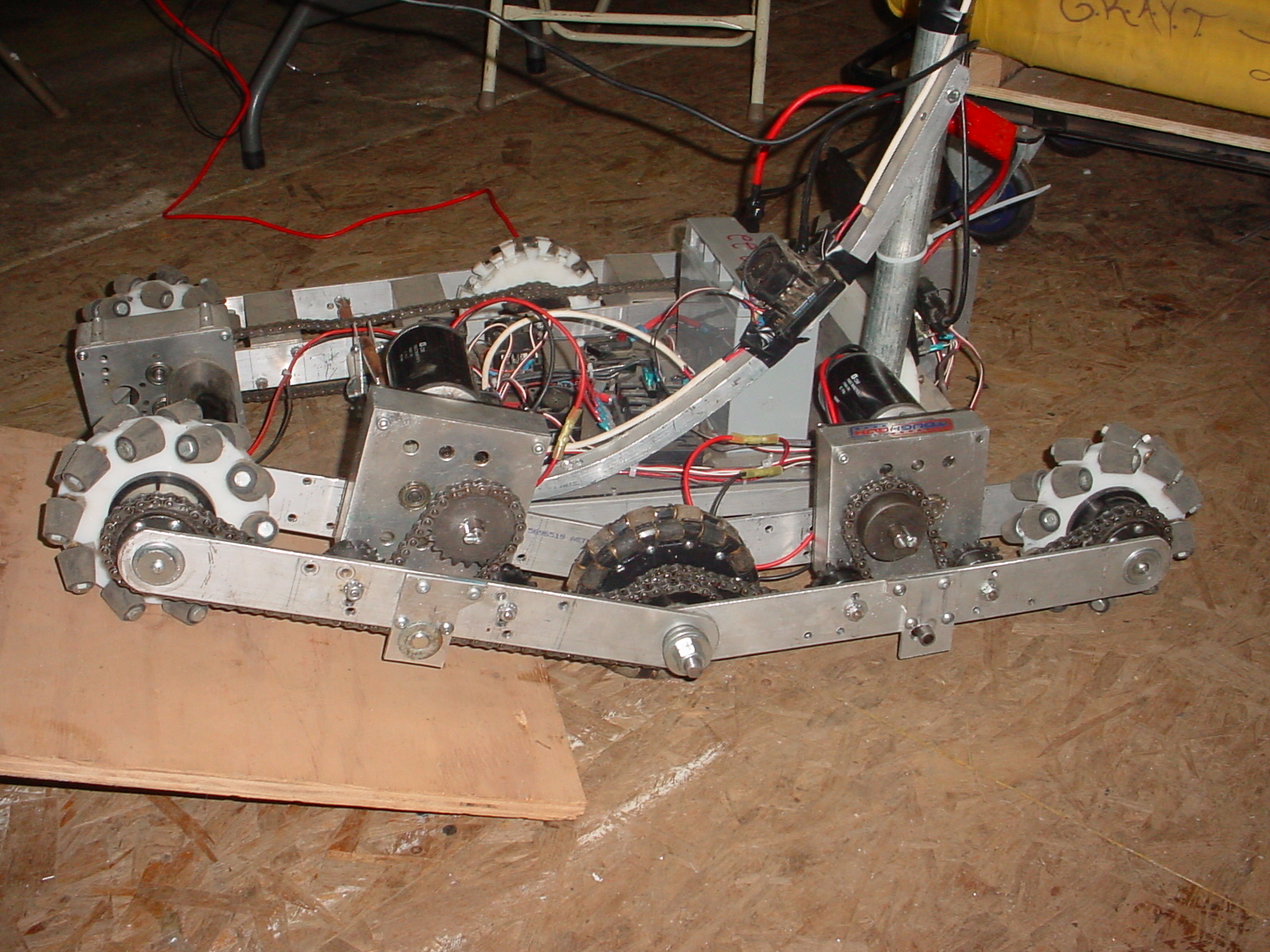
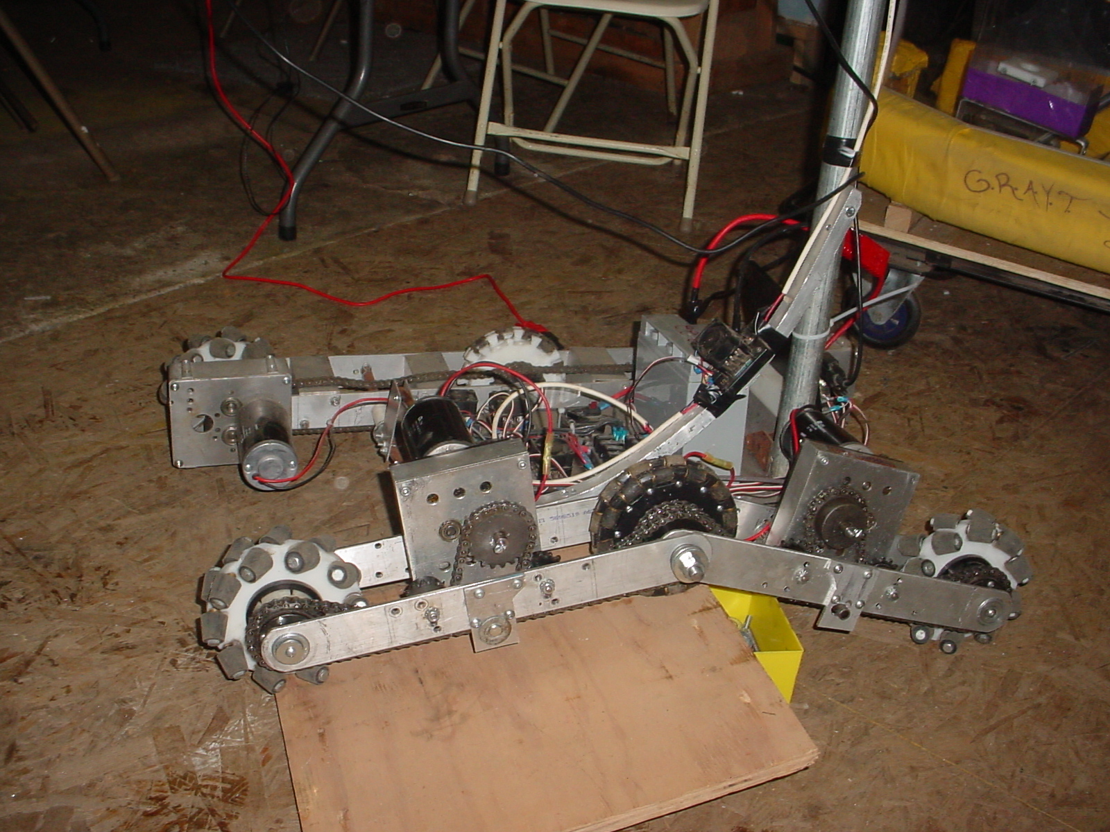
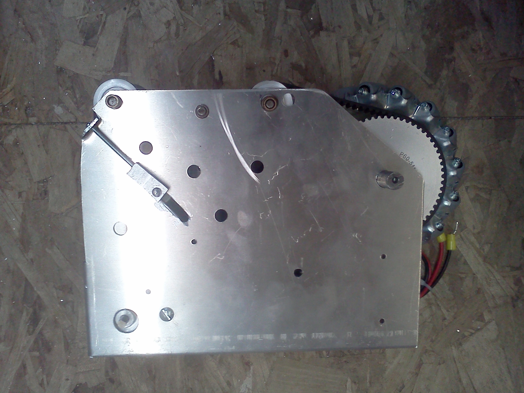
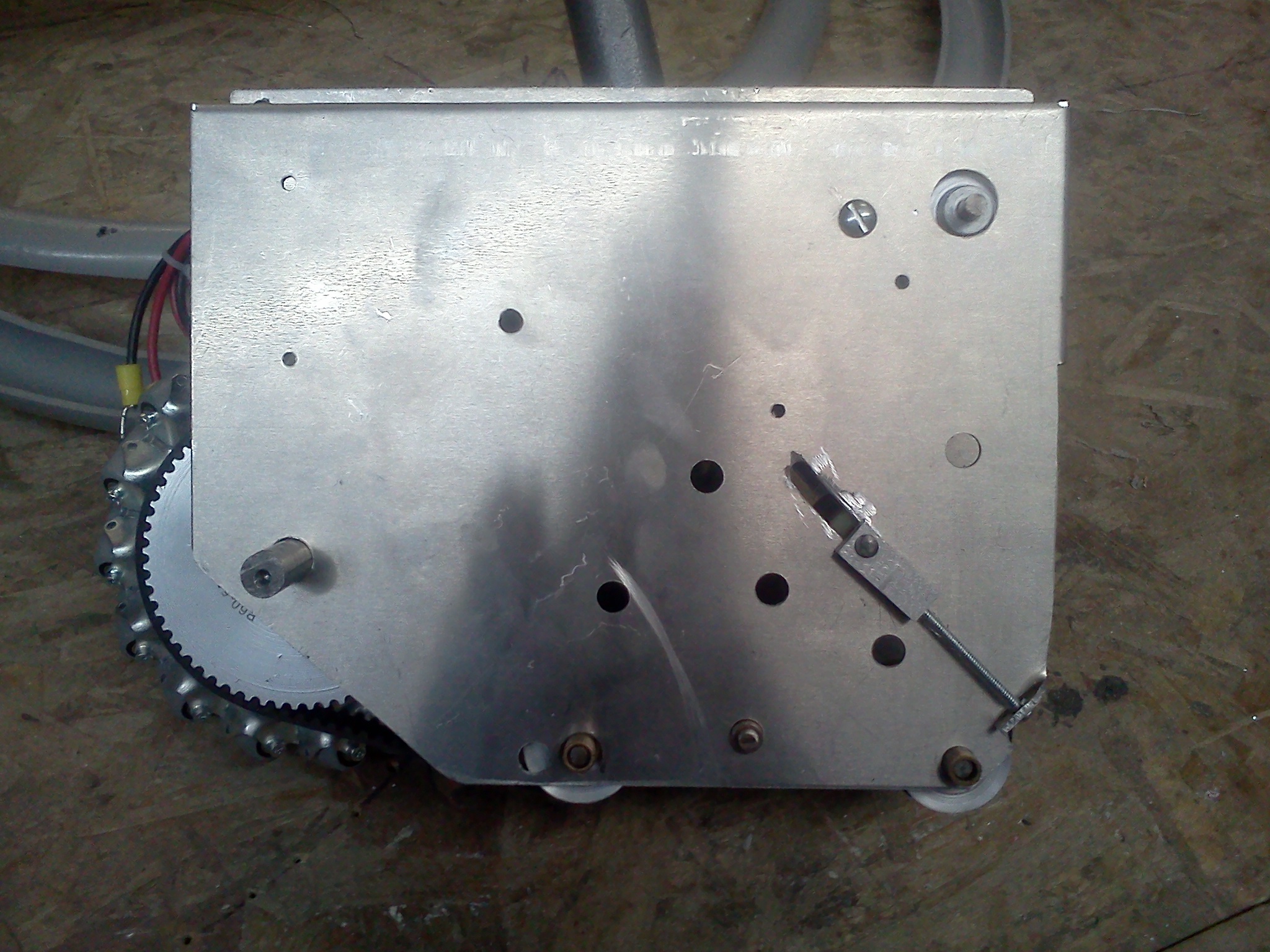
ANTI T-BONE FRAME
We have had trouble with robots locking us up by
T-Boning our robot. This new design should help us with
that problem. We had to make it wide instead of long
other wise there was not enough room for the drives and
it would make the robot too large to fit through a door.
The angles alow us to roll off the T-Boning robot.


.jpg)